5. Installation
Attention
Before working on the instrument, carefully read the safety points.
- It is forbidden to modify or repair the BactoSense.
- Perform the work steps in the exact order instructed.
- When replacing parts, use only genuine original parts supplied or recommended by bNovate.
5.1 Unpacking the BactoSense
Carefully follow the procedure below to unpack the BactoSense instrument from its packaging.
| WORK STEP | ADDITIONAL INFO / IMAGES | |
|---|---|---|
| 1. | Open the box and remove the lid. | 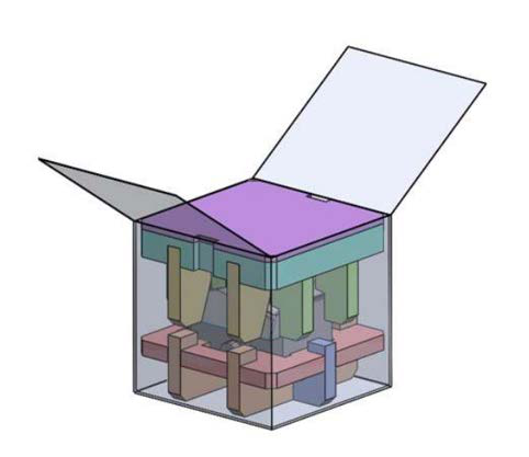 |
| 2. | Remove the compartments with accessories. | 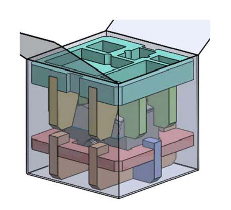 |
| 3. | Carefully remove the BactoSense from the box. | 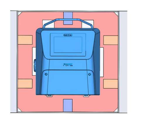 |
| 4. | Keep the packaging and foams for future use. |
5.2 Placement of the BactoSense
The BactoSense can be operated as a bench top instrument on a flat surface, or mounted to a wall or panel.
Note the following points for selecting an appropriate operating location:
- The BactoSense shall be installed in a vibration-free environment.
- The power supply must be stable, without spikes or interruptions.
- The BactoSense should not be exposed to direct sunlight during operation.
- In case of electromagnetic interference from a nearby object affecting the touchscreen (not responsive or flickering), relocate the BactoSense.
5.2.1 Mounting the BactoSense on a wall
The following procedure describes the mounting of the BactoSense to a vertical wall or panel:
WORK STEP | ADDITIONAL INFO / IMAGES | |
|---|---|---|
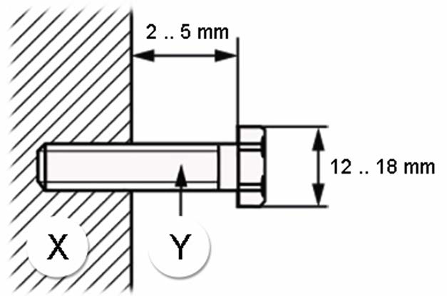
1. | Install two M8 screws at the same height, separated horizontally by 265 mm (10.4”) on a wall. The screw head diameter needs to be between 12 mm and 18 mm (0.47” – 0.71”) | Secure wall mounting The fixation must carry at least 60 kg (132 lbs). |
2. | Adjust the distance of the screws head and the wall according to the picture on the right. X: Wall Y: Screw |
|
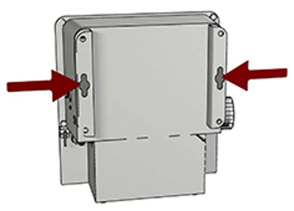
3. | Mount the BactoSense on the wall using its wall mounting system (red arrows). Tighten the two screws such that the BactoSense is firmly attached to the wall. |
|
5.3 Connecting the BactoSense to power
The BactoSense must be operated using the supplied original power supply unit to ensure:
- Compliance with the applicable standards for safety, EMC, ingress protection and RoHS, as listed in Compliance and applied standards.
- Instrument performance according to bNovate instrument validation protocols.
- Warranty coverage. Operation with alternative power supply units requires specific evaluation and permission by bNovate.
An uninterrupted and stable power supply as specified in Technical data must be guaranteed.
The power supply comes in an IP67 enclosure and a cable with either a plug type J, type E or type G. For connecting the BactoSense to power using one of these plugs supplied by bNovate, follow the instructions in Connecting using the standard plug of the power supply unit. For the connection using a different plug or power connectors, use the procedure described in Modifying the standard power supply unit with a different connector.
- The electrical plug or an additional circuit breaker should always be accessible to disconnect the main supply.
- The circuit breaker should respect the standards IEC60947-1 and IEC60947-3 and should protect a current of 10 A to 16 A.
5.3.1 Connecting using the standard plug of the power supply unit
The following procedure describes how to connect the BactoSense to power using the standard power supply unit and power plug of type J, E, G or B.
WORK STEP | ADDITIONAL INFO / IMAGES | |
|---|---|---|
1. | Make sure the power supply unit is dry and does not show any signs of damage. | |
2. | Plug the J, E, G or B-type plug of the power supply unit to a power source supplying the indicated voltage. | |
3. | Remove the cover of the power connector socket on the BactoSense. | |
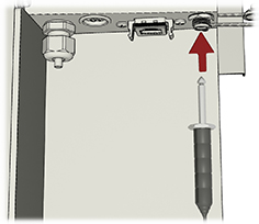
4. | Insert the power connector plug into the power connector socket. |
|
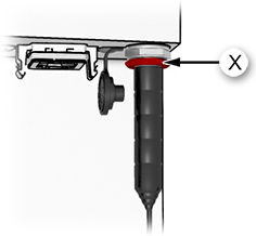
5. | Fasten the power connector plug lock ring (X). If the power connector is connected correctly and the instrument is powered, the instrument power button starts blinking. |
|
To disconnect the BactoSense from power, first switch the instrument off. Then unplug the power supply unit from the mains power source, before unplugging the power supply plug from the BactoSense.
5.3.2 Modifying the standard power supply unit with a different connector
The following procedure only applies, if the BactoSense shall be connected to a power source with a different plug than what has been delivered together with the standard power supply unit (J, E, G or B). In that case, the power supply unit is opened and the new connector installed manually.
- Only professional electricians are authorized to modify the power supply unit.
- It is forbidden to modify or repair the BactoSense instrument.
- Perform the work steps in the exact order instructed.
- Always use a plug with Protective Earth (PE).
- If the power supply cable is longer than 2 m, label it near the plug with the name of the device.
- If the power supply cable is longer than 20 m, the impedance of PE needs to be smaller than 0.2 Ω.
WORK STEP | ADDITIONAL INFO / IMAGES | |
|---|---|---|
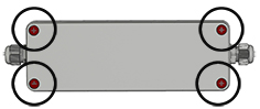
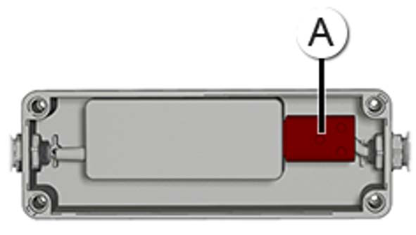
1. | Disconnect the power supply Ensure that the power supply is not connected to power. Remove the cover of the enclosure by unscrewing the four screws (circles). |
|
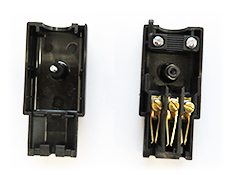
2. | Remove the C13 connector (A) and unscrew it to open. |
|
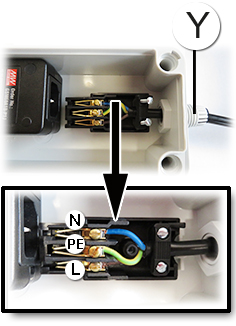
3. | Open the cable connector (Y) and insert the new cable. Cable lengths and wire cross sections: • 0 – 9 m (0 – 30 ft), 1 mm2 • 9 – 21 m (30 – 69 ft), 1.5 mm2 (maximal) The cable connector is dimensioned for a cable diameter of 3 – 10 mm (0.12” – 0.39”). | . |
4. | Connect protective earth Tighten the 3 wires (N, PE, L) in the electrical terminal and block the cable isolation. Ensure, that a plug with Protective Earth (PE) is used and the device is correctly connected to it. | |
5. | Close the C13 connector (A) using the screw and plug it in the power supply. Tighten the cable connector. Try to pull the cable to assess whether the cable connector is tight enough. |
|
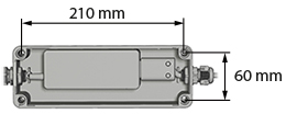
6. | Optional: the power supply can be mounted on a wall. M4 screws should be used with a minimum length of 20 mm. With the cover still removed, place the 4 screws and fix the enclosure to the wall. |
|
7. | Put the cover of the enclosure back and tighten the four screws to seal it. |
|
8. | Connect the power supply unit to power and the instrument as described in Connecting using the standard plug of the power supply unit. |
5.4 Installation of the manual sampling device
The manual sampling device is intended for measuring individual grab samples, collected in 5 mL screw-cap tubes. The following procedure describes how to install the manual sampling device.
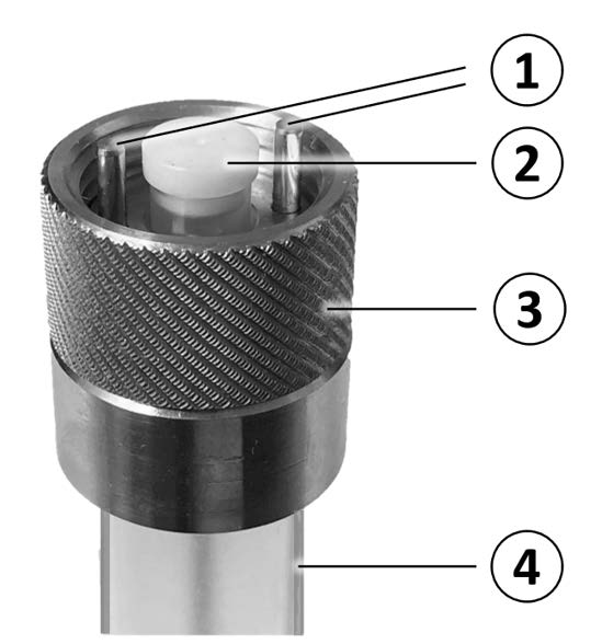
Figure 5-1 Manual sampling device 1: Positioning pins, 2: Plug, 3: Fixation ring, 4: 5 mL screw-cap tube.
Avoid contamination of the equipment. Wear nitrile gloves when handling samples, sampling devices and any components which come in contact with them.
WORK STEP | ADDITIONAL INFO / IMAGES | |
|---|---|---|
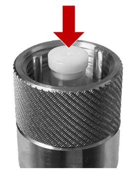
1. | Inspect the manual sampling device • Make sure it is free of dust and fibers. If not, clean it with a lint-free tissue wetted with sterile water or ethanol • Make sure the white sealing plug is sitting tightly in the connector |
|
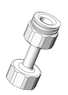
2. | Attach an empty 5 mL screw-cap tube or the Washstation at the sampling device. |
|
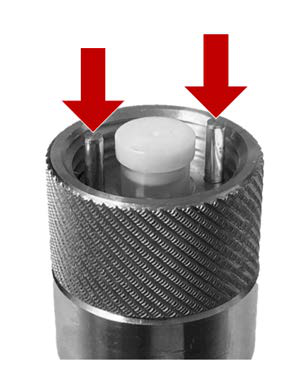
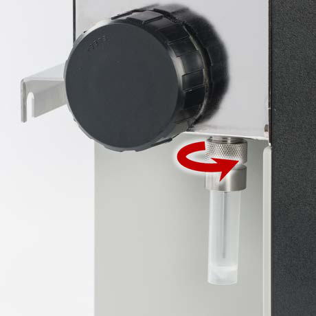
3. | Carefully insert the connector of the sampling device into the sampling device port on the left hand-side of the BactoSense by inserting the metallic positioning pins located inside of the sampling device connector into the openings on the BactoSense sampling device port. |
|
4. | Tighten by hand only Then tighten the knurled fixation ring until the sampling device is installed tightly. Finger-tightening only. Do not use any tools. |
|
5. | It is recommended to clean the sampling device after installation. If a Washstation is available, follow the procedure in Clean manual sampling device with Washstation, otherwise the procedure in Clean manual sampling device with basic cleaning. | |
6. | After the cleaning, it is recommended to perform a Prime prior to measuring the first sample. Follow the procedure in Performing a Prime. |
5.5 Installation of the online sampling device
The online sampling device is intended to measure samples continuously at predefined measurement intervals, and it is therefore directly connected to a water source and drain using an inlet and outlet tubing. The following procedure describes how to install the online sampling device.
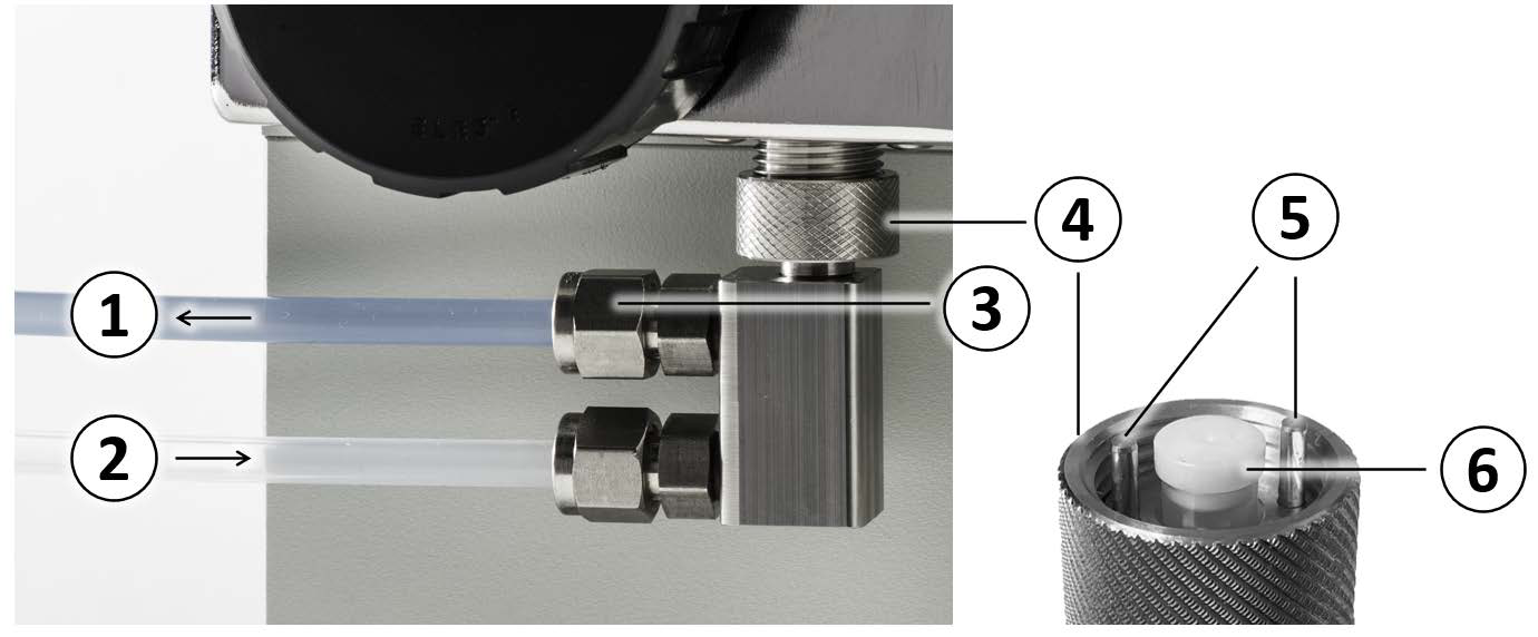
Figure 5-2 Online sampling device 1: Outlet tubing connected to a drain, 2: Inlet tubing connected to a water source, 3: Connector nut, 4: Fixation ring, 5: Positioning pins, 6: Plug.
Avoid contamination of the equipment. Wear nitrile gloves when handling samples, sampling devices and any components which come in contact with them.
Firmly attach tubings and sampling device
If the plumbing, tubings or sampling device are not tightly assembled or mounted, liquid can flood surrounding areas and cause material damage to nearby objects or infrastructure. All tube junctions must be carefully secured and tightened. The connections should be checked periodically after installation.
Connect outlet tubing to a drain
In drinking water installations, connect the outlet tubing to a drain to make sure that water which has been diverted from the drinking water pipe system is not returned after flowing through the additional fittings, tubings and BactoSense sampling device.
5.5.1 Attaching the tubings to the online sampling device
The following instructions describe how to attach the inlet and outlet tubings to the body of the online sampling device. Specifications of the tubings can be found in Technical data. The exchange of tubings in case they are contaminated or damaged is described in Replacing online sampling device tubings.
| WORK STEP | ADDITIONAL INFO / IMAGES | |
|---|---|---|
| 1. | Make sure the sampling device is not installed at the BactoSense. | |
| 2. | Unscrew the nuts of the two connectors on the sampling device. If necessary use a spanner. Be careful not to lose the ferrules located inside the nut. | 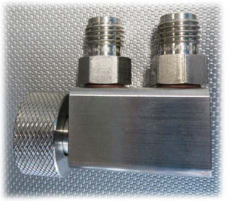 |
| 3. | Inspect the two tubings for contamination and damage. Only use clean and intact tubings with straight cuts. | |
| 4. | For both tubings, insert one end through a nut and a ferrule as illustrated. | 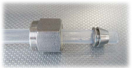 |
| 5. | Attach the blue tubing (outlet) to the connector closer to the attachment port of the sampling device. Attach the transparent tubing (inlet) to the more distant connector to the attachment port of the sampling device. Use a clamp to fasten the nuts. | 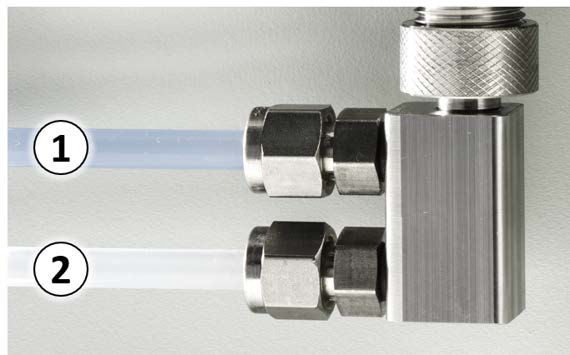 |
| 6. | If you want to attach the sampling device, proceed with Installing the online sampling device at the BactoSense. |
5.5.2 Installing the online sampling device at the BactoSense
In this section, the installation of the online sampling device with attached inlet and outlet tubings is described.
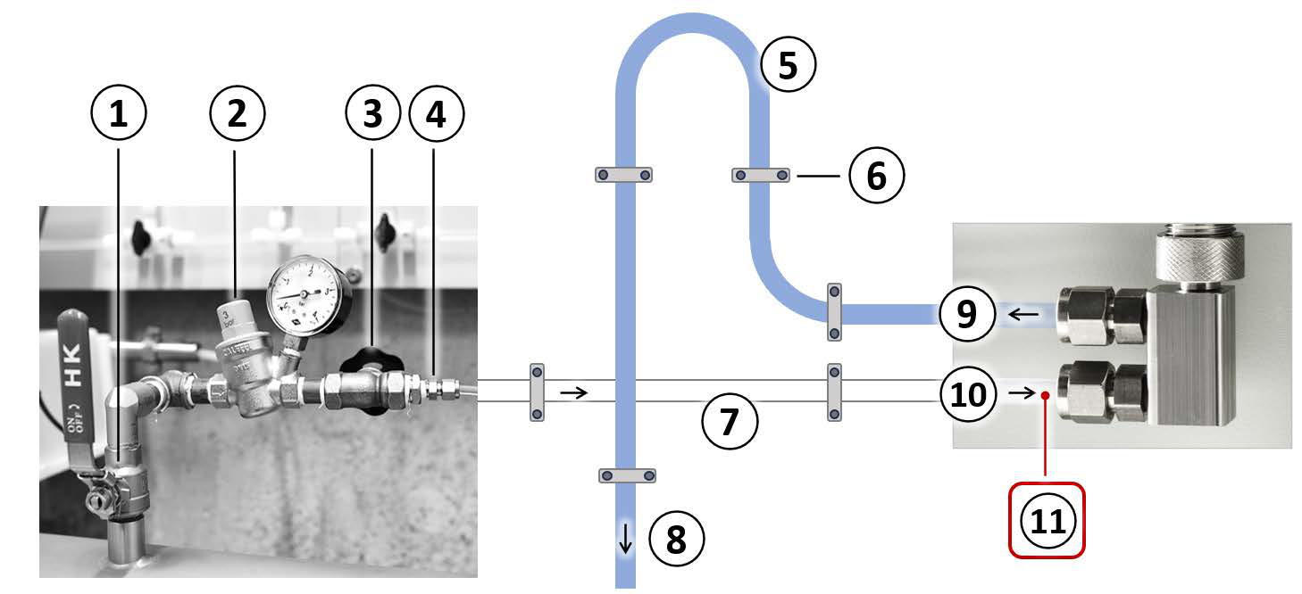
Figure 5-3 Typical installation for the online analysis mode using the online sampling device.
Flow and pressure adjustment
- On-off valve
- Pressure valve with gauge
- Flow valve
- Reduction fittings
In and outlet tubings
- Backpressure loop
- Tubing fixation
- Horizontal inlet tubing
- Outlet tubing connected to drain
Online sampling device
- Outlet tubing
- Inlet tubing
- Inlet conditions:
- Continuous flow
- 200 – 400 mL/min (0.05 – 0.10 gal/min)
- Max. 0.5 bar (7.3 psi)
Installation steps
-
Make sure the inlet and outlet tubings are firmly attached to the online sampling device.
-
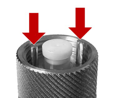
Carefully insert the connector of the sampling device into the sampling device port on the left hand-side of the BactoSense by inserting the metallic positioning pins located inside of the sampling device connector into the openings on the BactoSense sampling device port.
-
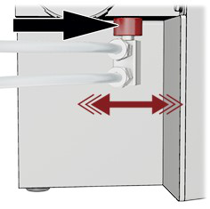
Tighten by hand only
Then tighten the knurled fixation ring (red) until the sampling device is installed tightly. Finger-tightening only. Do not use any tools.
-
Connect the sampling tubing safely
Carefully connect the free ends of the tubings to the inlet water source and outlet drain. • Level the inlet tubing with the water source to prevent trapping of air bubbles • Shorten the length of the tubings as much as possible • Install the outlet tube with a loop in high position • Minimize the amount of connectors to reduce potential sources of contamination • To prevent any damage to the sampling device and BactoSense, make sure no force is exerted via the tubings. Fixate the tubings to a solid structure in the proximity of the sampling device (30 – 50 cm) if possible. In drinking water installations, connect the outlet tubing to a drain to make sure that the water diverted from the drinking water pipe system is not returned after flowing through the additional fittings, tubings and BactoSense sampling device.
See figure 5-3.
-
Open the water supply carefully and check the appliance for leaks.
-
Check flow rate and pressure
Adjust the flow rate coming from the water supply. Flow rate range: 200 to 400 mL/min (0.05 – 0.10 gal/min) If the flow rate is not within the specified limits, results may be inaccurate or the BactoSense may be damaged. Make sure the pressure in the sampling device does not exceed 0.5 bar (7.3 psi). Install a pressure reducer if needed.
See figure 5-3.
5.6 Connectivity options
The BactoSense offers several options for integration and online data access.
Table 5-1 BactoSense connectivity options
| Connectivity Option | Documentation |
|---|---|
| I/O Box | I/O-Box |
| Modbus TCP | Modbus TCP |
| FTP | Retrieve data via FTP |
| HTTP and HTTPS | Retrieve files via HTTP or HTTPS |
| Virtual network computing (VNC) user interface relay (remote control) | GUI relay using VNC |
| Web user interface | Web User Interface |
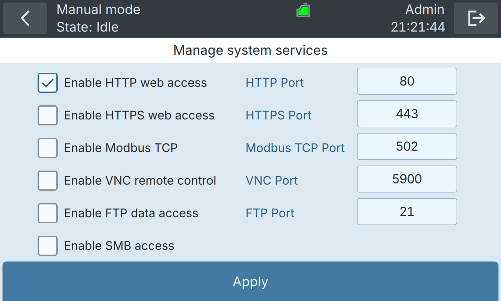
Figure 5-4 BactoSense system services configuration menu. Individual services can be enabled and communication ports configured.