6. I/O-Box
The IO-box is an accessory to the BactoSense. It can be used to connect the in- and outputs of the BactoSense to a PLC/SCADA system.
As an alternative to the I/O-Box, Modbus TCP can be used. Details can be found in Modbus TCP.
6.1 Technical specifications
Carefully read the technical specifications before preparing the integration.
6.1.1 Digital inputs
- Use: 4 digital inputs referenced to Common allow the instrument to be controlled by an external voltage (e.g. voltage coming out of a PLC).
- Specifications: optocoupler input: forward voltage 1.2 VDC with 3 kΩ in serial, cathode connected to COMMON, max. 30 mA, max. 50 mW.
Additional notes
- The Common (port 18) must be connected to the reference voltage of the input voltage (e.g. 0 V / Ground of the external power source).
- The digital inputs (ports 14 - 17) voltage range is between 5 - 30 V to produce a logic high level or "1". Otherwise it produces a logic low level or "0".
- If any of the digital inputs is at a logic high level or "1", the BactoSense enters "PLC- mode".
6.1.2 Digital outputs
- Use: 4 digital outputs allow the reporting of 4 different logic states, e.g. errors or alarms. As the output terminals are the output of a MOS-based solid-state relay (LH1540AAB), there is no polarity. Terminals A and B can be used in either direction and can be swapped. Terminals A and B are either in high-impedance (disconnected) or low- impedance (connected) state.
- Specifications: freely configurable, SSR output: max. 48 VDC, max. 300 mW, ON- resistance 2 Ω.
6.1.3 Analogue outputs
- Use: 2 analogue outputs (4 – 20 mA) allow the reporting of two analogue values, e.g. Total Cell Count and HNAP. Note: For the transmission of precise results, the use of Modbus TCP is recommended. See Modbus TCP
- Specifications: 2 x 0/4 – 20 mA, recommended 250 Ω load
6.1.4 IO-box schematics
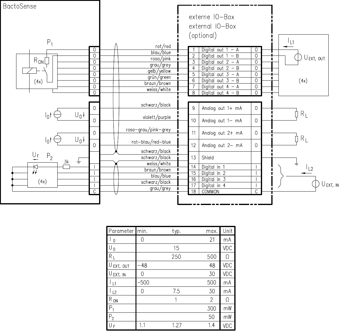
Figure 6-1 BactoSense IO-box schematics.
6.1.5 IO-box overview
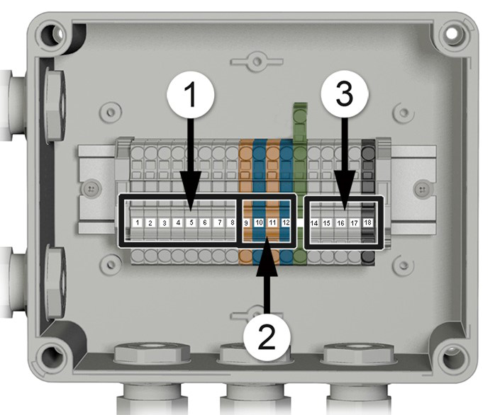
Figure 6-2 Overview of the BactoSense IO-box
① | Position of the digital outputs | ② | Position of the analogue outputs |
③ | Position of the digital inputs | ||
6.1.6 IO-box reference table
Table 6-1 IO-box reference table
| Terminal | Function | Terminal Color | Cable Color |
|---|---|---|---|
| 1 | Digital output 1 - A | Grey | Red |
| 2 | Digital output 1 - B | Grey | Blue |
| 3 | Digital output 2 - A | Grey | Pink |
| 4 | Digital output 2 - B | Grey | Grey |
| 5 | Digital output 3 - A | Grey | Yellow |
| 6 | Digital output 3 - B | Grey | Green |
| 7 | Digital output 4 - A | Grey | Brown |
| 8 | Digital output 4 - B | Grey | White |
| 9 | Analogue 1+ mA | Orange | Black |
| 10 | Analogue 1- mA | Blue | Purple |
| 11 | Analogue 2+ mA | Orange | Pink-Grey |
| 12 | Analogue 2- mA | Blue | Red-Blue |
| 13 | Shield | Green/Yellow | |
| 14 | Digital input 1 | Grey | White |
| 15 | Digital input 2 | Grey | Brown |
| 16 | Digital input 3 | Grey | Blue |
| 17 | Digital input 4 | Grey | Black |
| 18 | Common | Black | Grey |
6.2 Connecting the IO-box
Review the technical specifications in Digital inputs, Digital outputs and Analogue outputs and the schematics in IO-box schematics to ensure correct installation.
| WORK STEP | ADDITIONAL INFO / IMAGES | |
|---|---|---|
| 1. | Insert the two M16 plugs of the IO-box on the right-hand side of the instrument. | 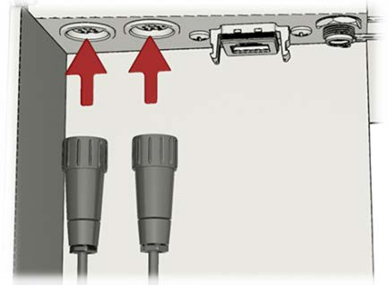 |
| 2. | Remove the cover of the enclosure by unscrewing the four screws (circles). | 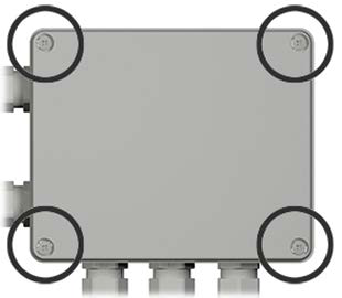 |
| 3. | Insert cable through the cable gland (A, B or C) and connect the wires to the corresponding terminal according to the IO-box reference table. | 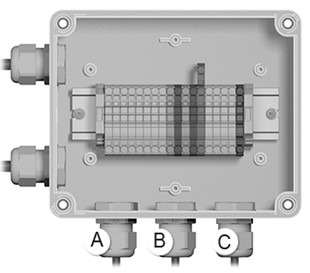 |
| 4. | Tighten the cable gland. Try to pull the cable to see if the cable gland is tight enough. | |
| 5. | Optional: the IO-box can be mounted on a wall. M4 screws should be used with a minimum length of 20 mm. With the cover still removed, place the 4 screws and fix the enclosure to the wall. | 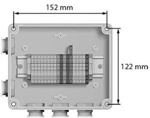 |
| 6. | Put the cover of the enclosure back and tighten the four screws to seal it. |
6.3 Connecting the outputs without IO-box
The BactoSense exposes the outputs on a 12 pin M16 female connector. The use of an IO- box is recommended however. The pinout of the connector is given below.
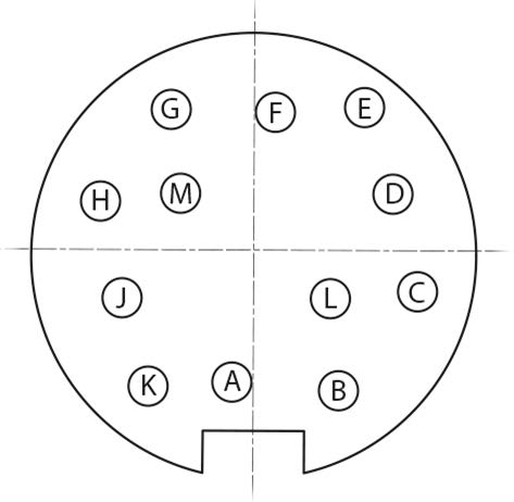
Figure 6-3 Overview of the output connector pinout
| A | Digital output 4 - B | G | Digital output 1 - B |
| B | Digital output 4 - A | H | Digital output 1 - A |
| C | Digital output 3 - B | J | Analogue 1+ |
| D | Digital output 3 - A | K | Analogue 1- |
| E | Digital output 2 - B | L | Analogue 2+ |
| F | Digital output 2 - A | M | Analogue 2- |
6.4 Connecting the inputs without IO-box
The BactoSense exposes the inputs on a 5 pin M16 female connector. The use of an IO-box is recommended. The pinout of the connector is given below.
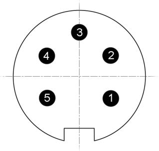
Figure 6-4 Overview of the input connector pinouts
- Digital input 1
- Digital input 2
- Digital input 3
- Digital input 4
- Common
6.5 Digital inputs configuration and PLC mode
The instrument can be controlled from an external Programmable Logic Controller (PLC). In order to avoid any conflicts when starting a process, the PLC first locks the instrument into “PLC Mode”, in which the instrument acts as a slave to the PLC. In this mode, all functions of the GUI related to running protocols and other processes are blocked. Once in PLC mode, protocols can be started and aborted from the PLC, using the Instrument’s digital inputs. The digital outputs then provide feedback to the PLC for safe operation.
The PLC mode is a remote-controlled Online mode: the PLC can request a single measurement, or start the scheduler to run protocols at predefined intervals. Measurements started from the PLC also appear in the Online mode results.
When no wires are connected to the digital inputs, their state is 0000.
Table 6-2 Overview of digital inputs states and associated functions.
DESCRIPTION | DIGITAL INPUTS | |||
|---|---|---|---|---|
1 | 2 | 3 | 4 | |
Force PLC mode: The instrument is idle but a slave to | 1 | 0 | 0 | 0 |
Run configurable protocol / measurement interval | 1 | 0 | 0 | 1 |
Run configurable protocol / measurement interval | 1 | 0 | 1 | 0 |
Run configurable protocol / measurement interval | 1 | 0 | 1 | 1 |
Run configurable protocol / measurement interval | 1 | 1 | 0 | 0 |
Run configurable protocol / measurement interval | 1 | 1 | 0 | 1 |
Run configurable protocol / measurement interval | 1 | 1 | 1 | 0 |
Abort current protocol | 1 | 1 | 1 | 1 |
Slave mode deactivated. End of PLC mode. | 0 | 0 | 0 | 0 |
To run a protocol several times, either use the scheduler option, or trigger a new measurement from the PLC by resetting the inputs state to 1000, then back to the corresponding “Run” state.
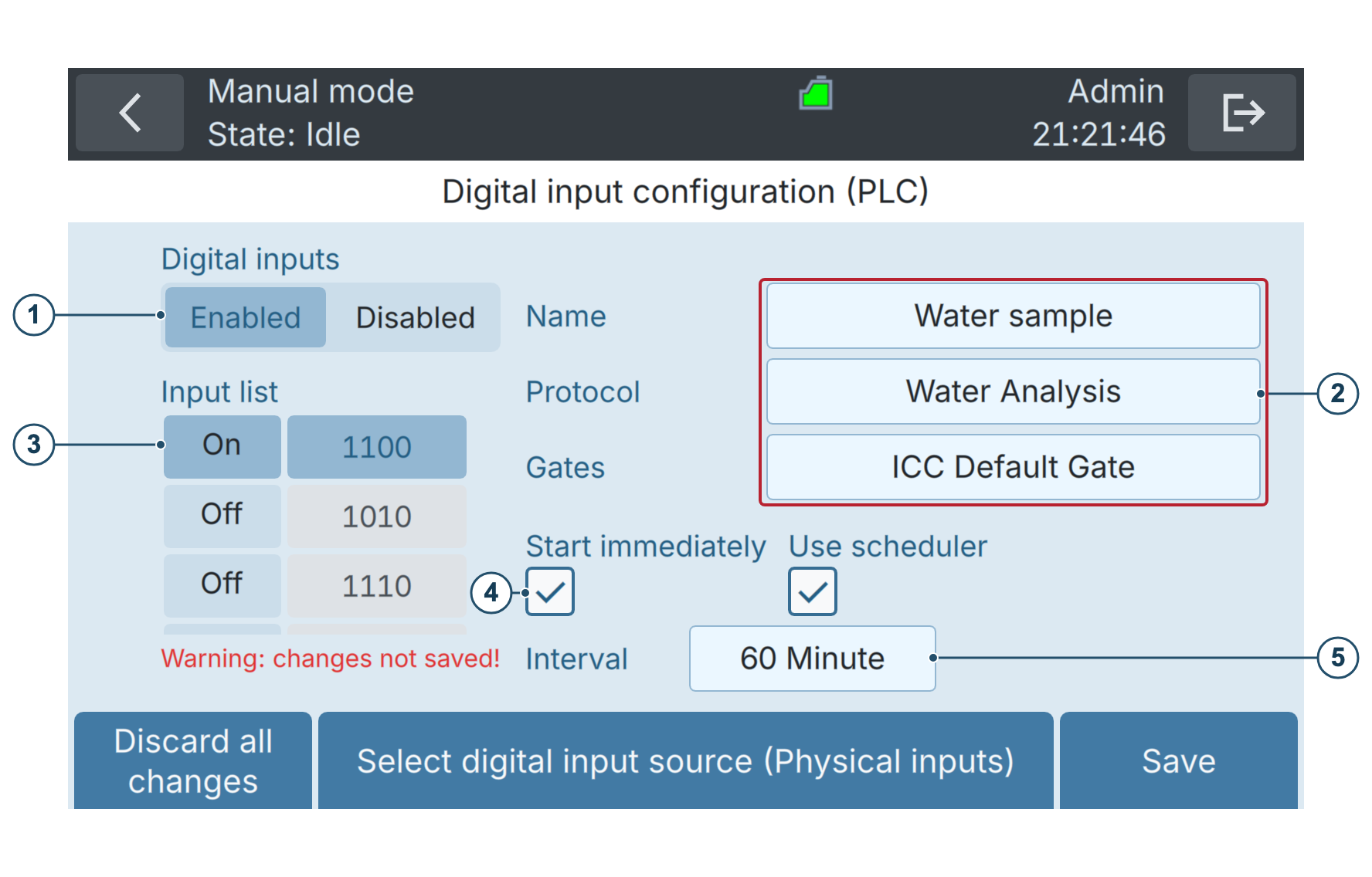
Figure 6-5 Digital inputs configuration
1 | Enable or disable digital inputs. If disabled, PLC mode is never active. | 2 | Protocol parameters: Name, Protocol, and Gates. |
3 | Select the inputs state you wish to configure. When the state selected in (3) is applied to the DI, the protocol defined in (2), (4) and (5) will be executed | 4 | If enabled, start the protocol immediately after the inputs state has changed. If not, wait for the duration of the scheduler interval before starting. |
5 | Scheduler settings: if the scheduler is activated, the protocol will be repeated at the selected interval, until the inputs state is changed. If the scheduler is disabled, the protocol will run only once. | ||
To configure the configurable digital inputs states, follow these steps:
| WORK STEP | ADDITIONAL INFO / IMAGES | |
|---|---|---|
| 1. | On the Home screen, press Settings. | |
| 2. | Press the Online mode settings button. | |
| 3. | Press the Digital inputs button. | |
| 4. | Make sure the toggle button is set to Enabled. | |
| 5. | Switch on and select the state you wish to configure in the Input list, enter a name for the sample, choose a protocol and choose a gate. | |
| 6. | If you want the protocol to repeat automatically, enable the “Use scheduler” check box, and choose an interval. | |
| 7. | In the above case, choose if you want the protocol to execute immediately or at the end of the first interval with the “Start immediately” check box. | This option is only useful if the scheduler is activated. |
| 8. | Press the Save button. |
6.6 Digital output configuration
The values of digital outputs are modified in the following situations:
-
When the instrument is powered off, all outputs are set to 0.
-
When the instrument is powered on, the outputs show the current error state: none / critical / non-critical.
-
At the end of a measurement in Online mode, the outputs are changed to indicate errors and alarms, according to user-defined settings.
-
When Reset is clicked on the output test screen or when Save is pressed on the digital output settings, the outputs are updated to show the error state only (alarms are ignored).
-
After manually clearing the errors, the outputs are automatically reset (and therefore show the new error state and no alarms).
-
At specific times during the measurement, extra signals can be relayed. By default, neither of them is relayed to the outputs. These are:
-
Process running. Active when a protocol is running.
-
Sampling device in use. Active when the sampling device is being used. It drops back to inactive after the sample preparation step of measurement protocols.
-
Low cartridge. Active when the cartridge level is below 15 %, or if the cartridge is estimated to be empty within a month based on the current measurement frequency.
-
Expired cartridge. Active when the cartridge is expired.
-
The digital output state at the end of a measurement is defined according to these default values, which can be changed in the settings:
-
If there are no errors and no alarms, all terminals are set to the user-defined base state. By default, this is 1 everywhere.
-
In case of a critical error, the first output is set to 0.
-
Non-critical errors set the second output to 0.
-
Alarms set the third and fourth output to 0.
-
In case of conflict in the output settings, priority is given to:
-
Critical errors
-
Non-critical errors
-
Cartridge states
-
Alarm
-
Only Admin users can change the output settings, as these can critically affect external PLC systems.
The following procedure describes how to adjust the digital outputs.
WORK STEP | ADDITIONAL INFO / IMAGES | |
|---|---|---|
1. | On the Home screen, press Settings. | |
2. | Press the Online mode settings button. | |
3. | Press the Digital outputs button. | |
4. | Set Base state for outputs 1–4 when no errors or alarms are active. | 1: The switch is closed. 0: The switch is open.
|
5. | Set the response of each output in the Critical error row. | By default, a critical error opens output 1. 1: The switch is closed. 0: The switch is open. /: The switch is not affected by this error.
|
6. | Set the response of each output in the Non-critical error row. | By default, a non-critical error opens output 2.
|
7. | Assign each enabled alarm to the required outputs in its alarm row. | You can only assign alarms that are enabled. You can assign several alarms to the same output. Example alarm rows: High TCC (top), High HNAP (bottom).
|
8. | Press the Save button. |


6.7 Analogue output configuration
The analogue current output is changed in the following situations:
- When the instrument is powered off, both outputs are set to 0 mA.
- When the instrument is powered on, both outputs are set to 2 mA.
- When a measurement in Online mode terminates after cell counting, the value is set between 4 and 20 mA, according to range and source definition of the analogue output settings. If the measurement fails due to an error before cell counting begins, the output remains at its previous value.
- When a user manually tests the output, the current is set to whatever value the user has chosen. The reset button sets them to 4 mA.
For the transmission of precise results, the use of Modbus TCP is recommended. See Modbus TCP
Only Admin users can edit the analogue 4 .. 20 mA outputs.
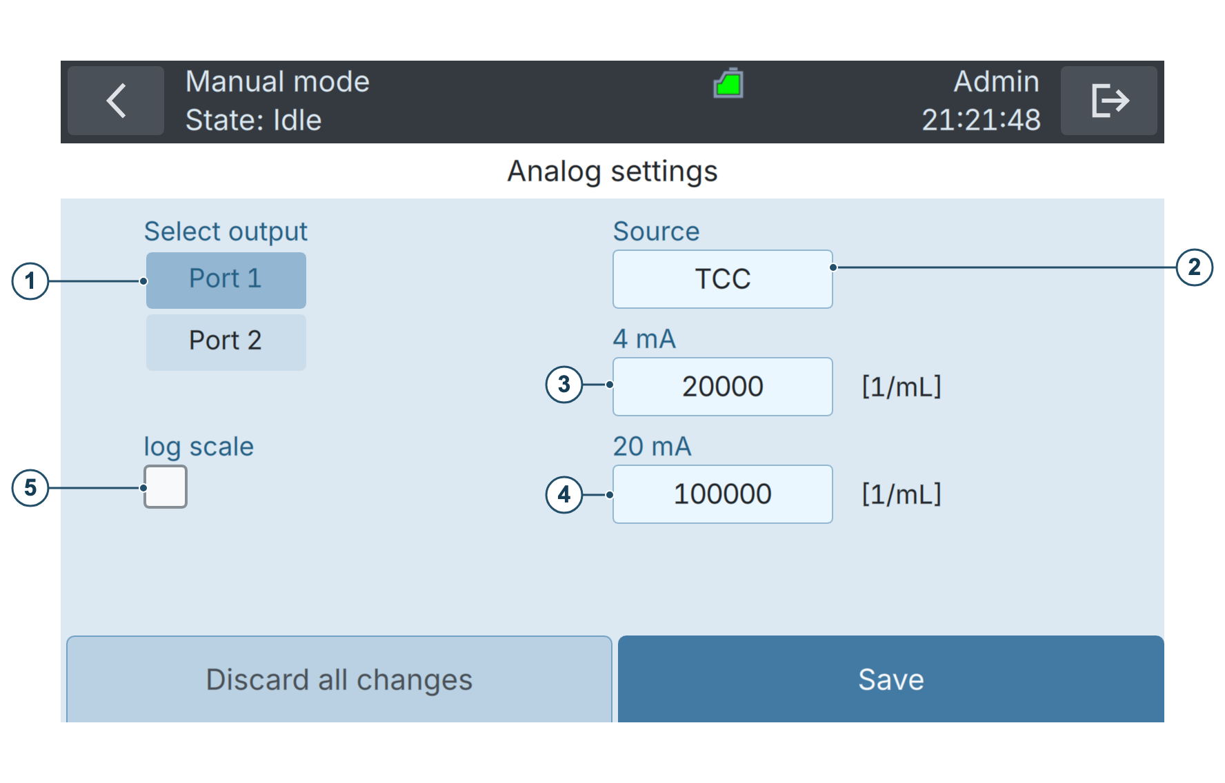
Figure 6-6 Analogue output settings
1 | Output port selection | 2 | Source: Defines which measurement |
3 | Lower limit 4 mA: Which value of | 4 | Upper limit 20 mA: Which value of |
5 | If selected, interpolates the chosen cell count value range with a logarithmic scale as follows: | ||
The following procedure describes how to adjust the analogue outputs.
| WORK STEP | ADDITIONAL INFO / IMAGES | |
|---|---|---|
| 1. | On the Home screen, press Settings. | |
| 2. | Press the Online mode settings button. | |
| 3. | Press the Analog outputs button. | |
| 4. | Choose Port 1 or Port 2 (figure 6-6) | |
| 5. | Choose the source (figure 6-6, position 2). | |
| 6. | Define the lower limit of the range (figure 6-6, position 3). | When the source is equal to this value, 4 mA will be output on the selected port. |
| 7. | Define the upper limit of the range (figure 6-6, position 4). | When the source is equal to this value, 20 mA will be output on the selected port. |
| 8. | Press the Save button. |
6.8 Digital and analogue output testing
Log in as Admin and use Test outputs while the instrument is idle, with PLC mode disabled.
The Test outputs interface allows to generate a physical output signal for testing purposes. Make sure that such tests do not generate an alarm on your control system.
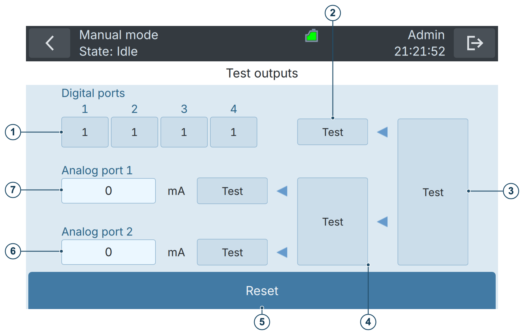
Figure 6-7 Testing analogue and digital outputs
1 | Define state of digital outputs for | 2 | Set digital outputs to the state |
3 | Set all digital and analogue | 4 | Set current on both analogue |
5 | Reset outputs to their state before | 6 | Set current on port 2. |
7 | Set current on port 1. | ||
The following procedure describes how to test the analogue and digital outputs.
| WORK STEP | ADDITIONAL INFO / IMAGES | |
|---|---|---|
| 1. | On the Home screen, press Settings. | |
| 2. | Press the Online mode settings button. | |
| 3. | Press the Test outputs button. | |
| 4. | Enter the test values that you wish to send to the PLC. | For digital outputs: 1: The switch is closed. 0: The switch is open. |
| 5. | Tests can be triggered individually or together (see figure 6-7): • Testing only the digital outputs on the terminals 1 – 4. • Testing only the analogue outputs on ports 1, 2 or both. • Testing all outputs. | The output signals can be measured on the terminals. |
| 6. | Press the Reset button. |