2. Instrument Overview
2.1 BactoSwitch product overview
An overview of the BactoSwitch elements is shown below:
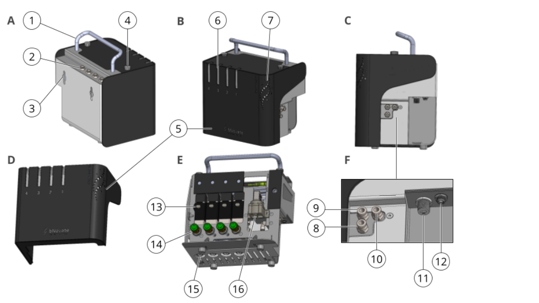
Figure 2-1 BactoSwitch elements
| 1 | Handle | 2 | Input lines connectors |
| 3 | Wall mount | 4 | Front cover fixation knob |
| 5 | Removable front cover | 6 | Selected line light indicator |
| 7 | Status light indicator | 8 | Water line to BactoSense |
| 9 | Water line from BactoSense | 10 | Water line output to drain |
| 11 | USB-C socket | 12 | Power socket |
| 13 | Manual line open/close override | 14 | Flow rate adjustment knob |
| 15 | Pressure regulator set clearance | 16 | Flow meter |
2.2 Light indicators
The behaviour of the light indicators is summarized in Table 2-1. Numbers refer to Figure 2-1, view B.
Table 2-1 Light indicator behaviour
| LIGHT INDICATOR | BEHAVIOUR |
|---|---|
| Line selection lights (6) | Blue: line open Off: line closed |
| Status light (7) | Green light: idle Slow blinking green light: measurement in progress, no sampling Fast blinking green light: measurement in progress, sampling water from the line Red light: measurement error |
2.3 Working principle
The scheme below shows the basic operation of the BactoSwitch (front cover removed for clarity). Water from each input line (1) flows through a check valve (2, not visible), through a pressure regulator (3), then through a needle flow valve (4) and finally through a solenoid valve (5). Each input line can be open or closed. Water from the open lines combines and flows out of the BactoSwitch to the online sampling device of the BactoSense (6). After flowing through the sampling device, water flows back to the BactoSwitch, through the flowmeter (7), and finally to the drain (8).
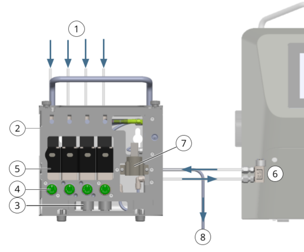
Figure 2-2 BactoSwitch working principle. See text above for explanations.
Solenoid valves of unused input lines must be closed manually and the corresponding lines disabled in the software. See Installation of the input lines and Line configuration for more information.
2.4 Type plate of the BactoSwitch
The type plate of the BactoSwitch can be found on the right-hand side of the instrument.
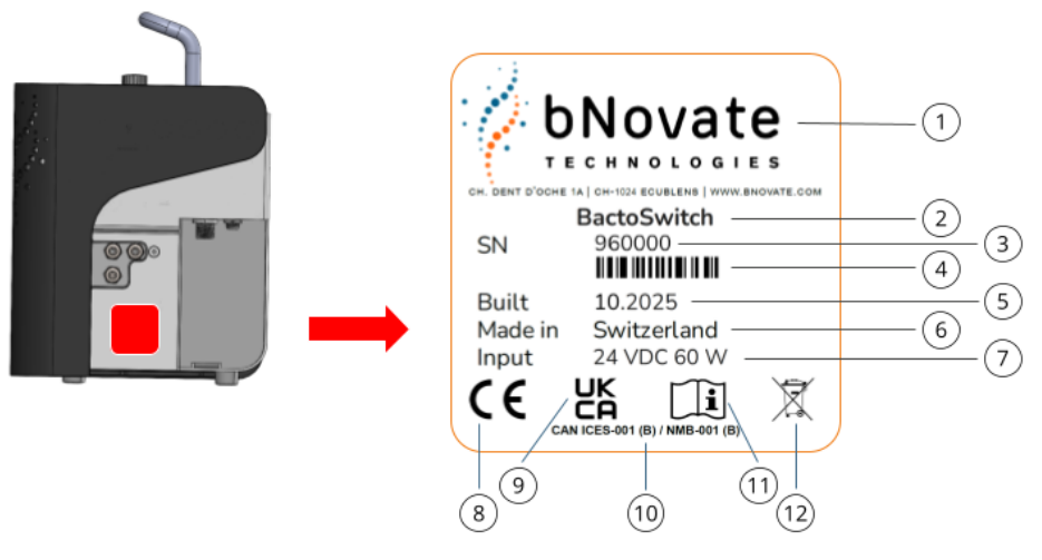
Figure 2-3 Type plate of the BactoSwitch
| 1 | Manufacturer | 2 | Product name |
| 3 | Serial number | 4 | Barcode |
| 5 | Manufacturing date | 6 | Country of origin |
| 7 | Voltage and power requirements | 8 | CE mark |
| 9 | UKCA mark | 10 | Compliance with Canadian EMC and interference standards |
| 11 | Read the instructions and operate with caution | 12 | Disposal information |
2.5 Type plate of the BactoSwitch power supply
The type plate of the BactoSwitch power supply can be found on the power supply and has the following elements:
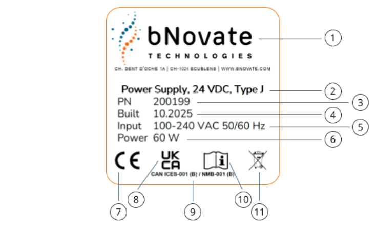
Figure 2-4 Type plate of the BactoSwitch power supply unit
| 1 | Manufacturer | 2 | Product name |
| 3 | Part number (varies with plug type) | 4 | Manufacturing date |
| 5 | Service input voltage and frequency | 6 | Power consumption |
| 7 | CE mark | 8 | UKCA mark |
| 9 | Compliance with Canadian EMC and interference standards | 10 | Read the instructions and operate with caution |
| 11 | Disposal information |
2.6 Technical data
Table 2-2 Technical data of the BactoSwitch
| PROPERTY | SPECIFICATION |
|---|---|
| GENERAL | |
| Required hardware version | BactoSense CORE/SMART, serial number 910500 onwards |
| Required software version | 3.1.0-BS and above |
| Operating environment | Indoor use |
| Operating altitude | Max. 2000 m (6600 feet) above sea level |
| Operating temperature | 5 °C – 30 °C (41 °F – 86 °F) |
| Operating humidity | 10 % – 90 % RH |
| Storage temperature | 5 °C – 30 °C (41 °F – 86 °F) |
| Storage humidity | 10 % – 70 % RH |
| Ventilation requirements | None |
| Sound pressure level | < 64 dBA |
| Protection class | Instrument: IP65 Power supply: IP67 |
| SAMPLING | |
| Sampling type | Online |
| Sample conditions | Water only Temperature: 5 °C – 40 °C (41 °F – 104 °F) Turbidity: 0 – 10 FTU, 0 – 10 FNU Conductivity: 0 – 100’000 μS/cm at 20 °C pH value: 5 – 12 Chlorine: max. 3 mg/L Iron: max. 200 μg/L Manganese: max. 50 μg/L Solid particles: < 0.5 mm |
| Number of inputs | 4 |
| Input pressure range | 0.1 – 5 bar |
| Individual line flow rate range | 150 – 400 mL/min |
| Pressure regulator | Built-in and pre-adjusted (non-relieving) |
| Flow control | Adjustable needle valve |
| Line selection | Normally open, media-separated solenoid valves Manual override close command |
| Fluidic interfaces | Push-in fitting ø6x1 mm |
| Inlet tubings | Material: PFA (transparent) Outer diameter: 6 mm Inner diameter: 4 mm Maximum length: 4 m Quantity: 4x |
| Online sampling device tubings | Material: PFA (transparent) Outer diameter: 6.35 mm (1/4″) Inner diameter: 4.35 mm Recommended length: 200 mm Quantity: 2x |
| Outlet tubing to drain | Material: PFA (transparent) Outer diameter: 6 mm Inner diameter: 4 mm Maximum length: 2 m Quantity: 1x |
| Wetted materials | PFA, SS 316L, SS 316Ti, FKM, EPDM, ENP-brass, PPS 40 % GF, PVDF, zirconia ceramic |
| CLEANING | |
| Agents and conditions | Water (temperature: 1 °C – 85 °C, pressure: max. 2 bar, time: max. 15 min) Chlorine: max. 10’000 mg/L of active chlorine (temperature: max. 25 °C) |
| PHYSICAL | |
| Dimensions (W x D x H) | 264 x 206 x 300 mm (10.4 x 8.1 x 11.8″) |
| Weight | 12 kg (26.5 lbs) |
| Power supply dimensions (W x D x H) | 230 x 80 x 65 mm (9.0 x 3.1 x 2.6″) |
| Power supply weight | 0.9 kg (2.0 lbs) |
| ELECTRICAL | |
| Installation category | II |
| Pollution degree | 2 |
| Power supply | Power supply unit: 100 – 240 VAC ± 10 %, 50/60 Hz, 1.4 A BactoSwitch: 24 VDC, 60 W |
| Power consumption | Max. 60 W |
| INTERFACES | |
| USB | 1 x USB 2.0 type C (female) |