4. Installation
Attention
Before working on the instrument, carefully read the safety points.
- Perform the work steps in the exact order instructed.
- When replacing parts, use only genuine original parts supplied or recommended by bNovate.
- Modification or repair of the BactoSwitch by non-agreed service technicians is at the customer’s risk and responsibility and voids the warranty.
- Use the original packaging of the BactoSwitch when returning components.
4.1 Packing list
Table 4-1 BactoSwitch packing list
| ART. NO | NAME | IMAGE |
|---|---|---|
| 200195 | BactoSwitch | 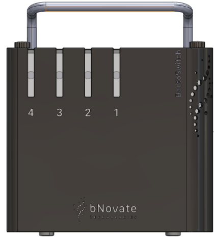 |
| 200199 – Type J plug (CH) or 200200 – Type E plug (EU) or 200201 – Type G plug (UK) or 200202 – Type B plug (USA) | Power supply unit Note: To avoid confusion with the BactoSense power supply, the BactoSwitch power connector tip has a white ring. | 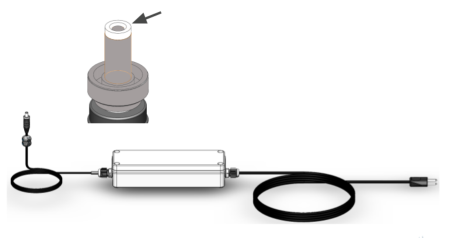 |
| 101265 | Waterproofed dual head USB-C cable, L = 50 cm | 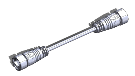 |
| 101368 | PFA tubing roll ø6 mm x 4 mm, 15 m | 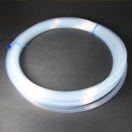 |
| 101382 | Tube cutting tool | 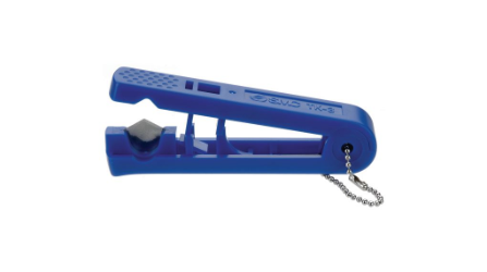 |
| 101367 | Online sampling device with pre-installed 200 mm long OD ¼″ tubings and protective cap | 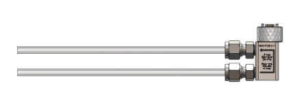 |
| 101022 (Cardboard) 101362 (Foam set) | BactoSwitch packaging |
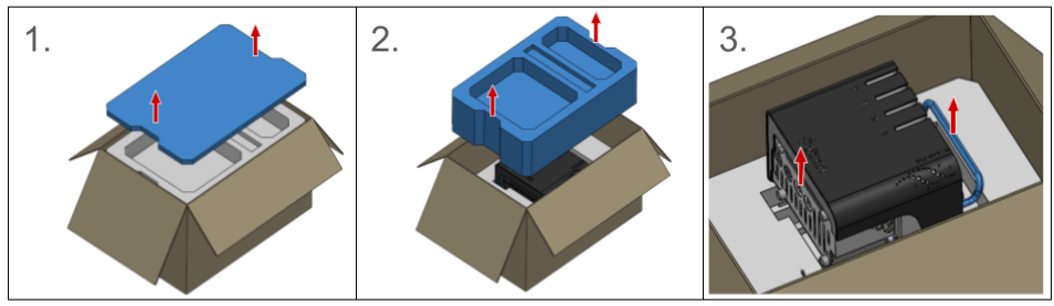
4.2 Unpacking
| WORK STEP | |
|---|---|
| 1. | Open the box and remove the lid. |
| 2. | Remove the compartments with accessories. |
| 3. | Carefully remove the BactoSwitch from the box. |
| 4. | Store the packaging and foams for future use. |
4.3 Placement of the BactoSwitch
The BactoSwitch can be operated as a benchtop instrument on a flat surface, or mounted to a wall or panel.
Note the following points for selecting an appropriate operating location:
- The BactoSwitch shall be installed in a vibration-free environment.
- The power supply must be stable, without spikes or interruptions.
- The BactoSwitch should not be exposed to direct sunlight during operation.
4.3.1 Mounting the BactoSwitch with BactoSense on a wall or panel
The following procedure describes the mounting of the BactoSwitch to a vertical wall or panel, next to a BactoSense. Please also consult Mounting the BactoSense on a wall in the BactoSense user manual.
| WORK STEP | ADDITIONAL INFO / IMAGES | |
|---|---|---|
| 1. | The 4 fixation points for a BactoSwitch with BactoSense are shown in Figure 4-1 below this table. The screw head diameter needs to be between 12 mm and 18 mm (0.47″ – 0.71″), and the screw head needs to be less than 7 mm (0.28″) thick. | Secure wall mounting Each fixation screw must be able to carry at least 30 kg (66 lbs). |
| 2. | Adjust the distance between the screw heads and the wall according to the picture on the right. X: Wall Y: Screw | 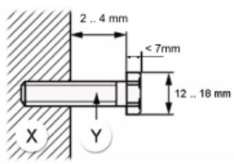 |
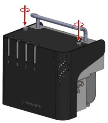
| 3. | Unscrew and remove the two knob screws on top of the front cover. | 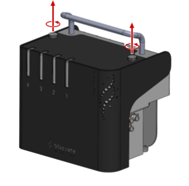 |
| 4. | Detach the front cover from the BactoSwitch. | 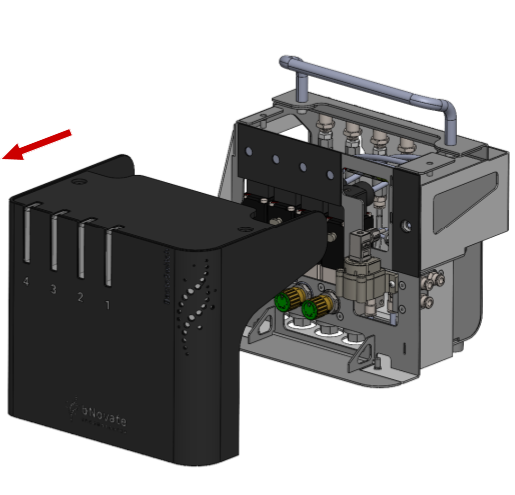 |
| 5. | Remove the two screws from both sides of the structure, using a 2.5 mm hex key. | 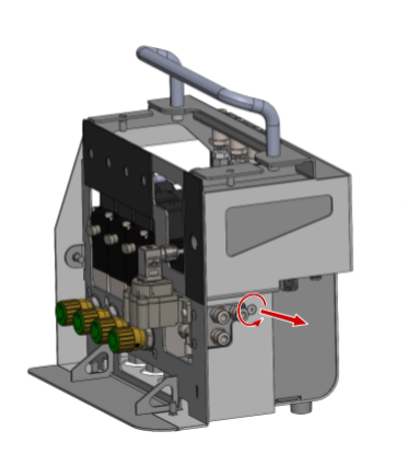 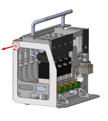 |
| 6. | Detach the rear structure from the rest of the assembly by lifting it with the handle. | 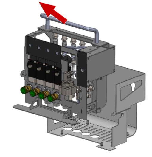 |
| 7. | Mount the rear structure on the wall using its wall mounting system (red arrows). Tighten the two screws such that the structure is firmly attached to the wall. | 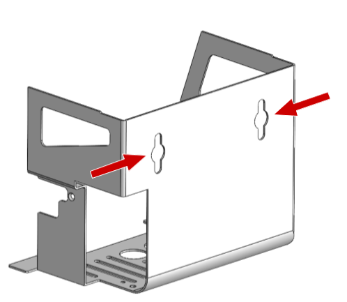 |
| 8. | Place the main assembly back into the rear structure now fixed to the wall. | 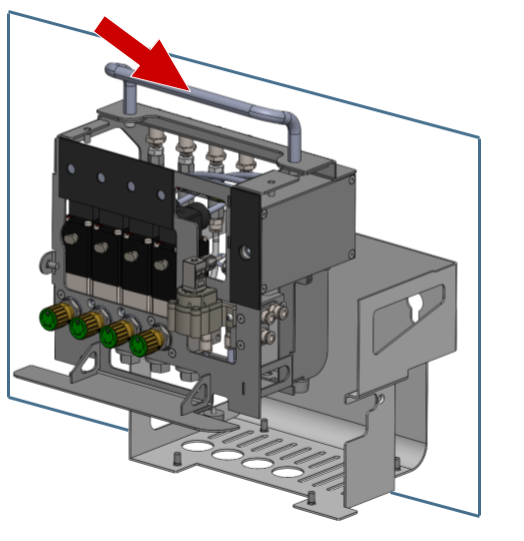 |
| 9. | Re-install the two screws removed in step 5. |
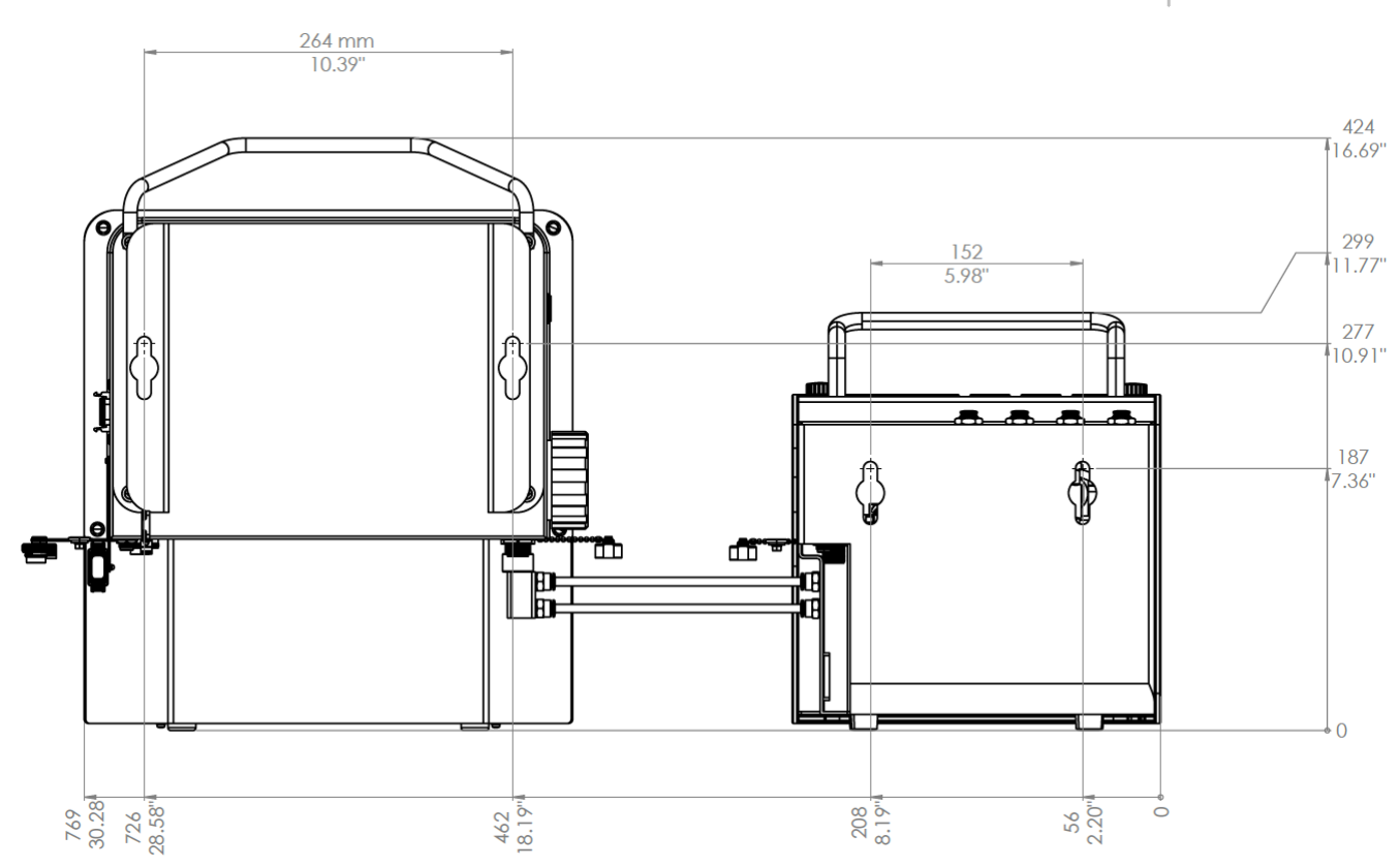
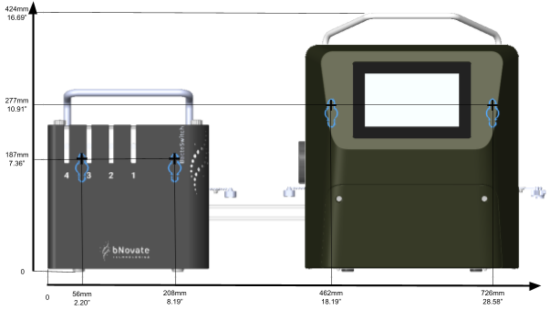
Figure 4-1a Location of BactoSwitch and BactoSense mounting points for serial numbers up to 960015. Top: back view (horizontal axis reversed). Bottom: front view.
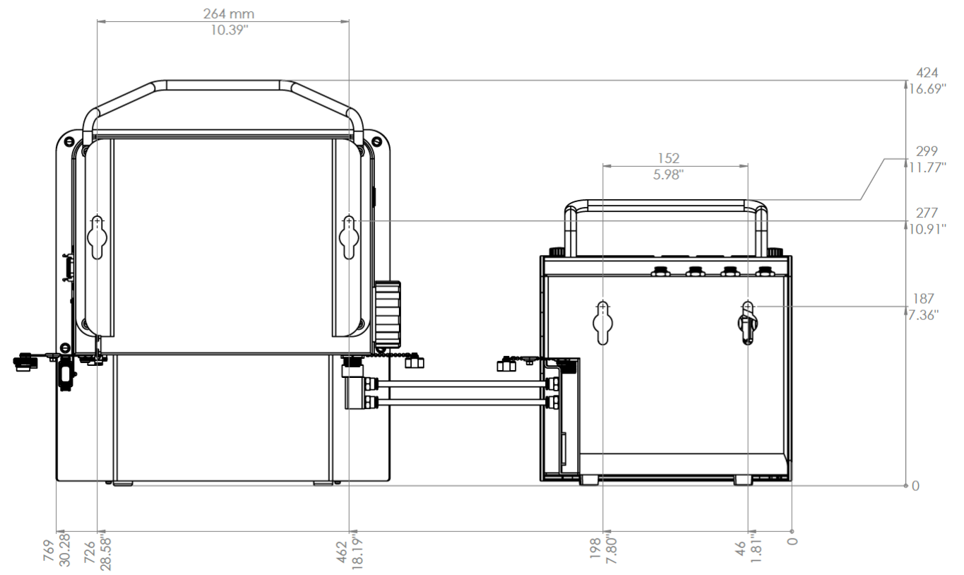
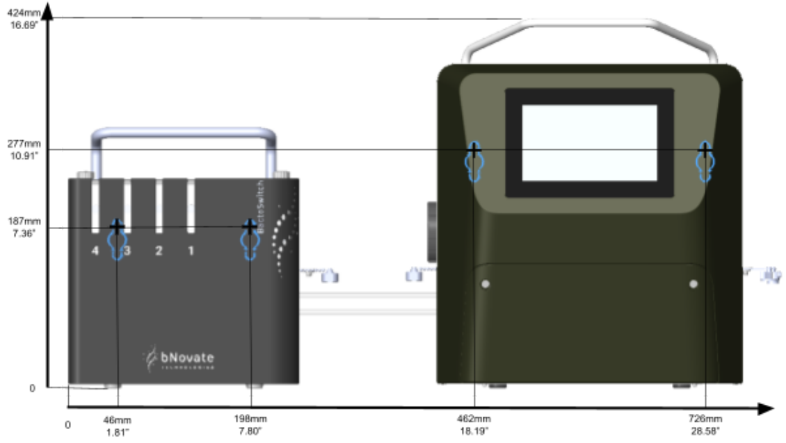
Figure 4-1b Location of BactoSwitch and BactoSense mounting points for serial numbers from 960016 and above. Top: back view (horizontal axis reversed). Bottom: front view.
4.4 Installation of the fluidic lines
Figure 4-2 provides a schematic illustration of the fluidic lines installation. Detailed explanations and instructions are given below.
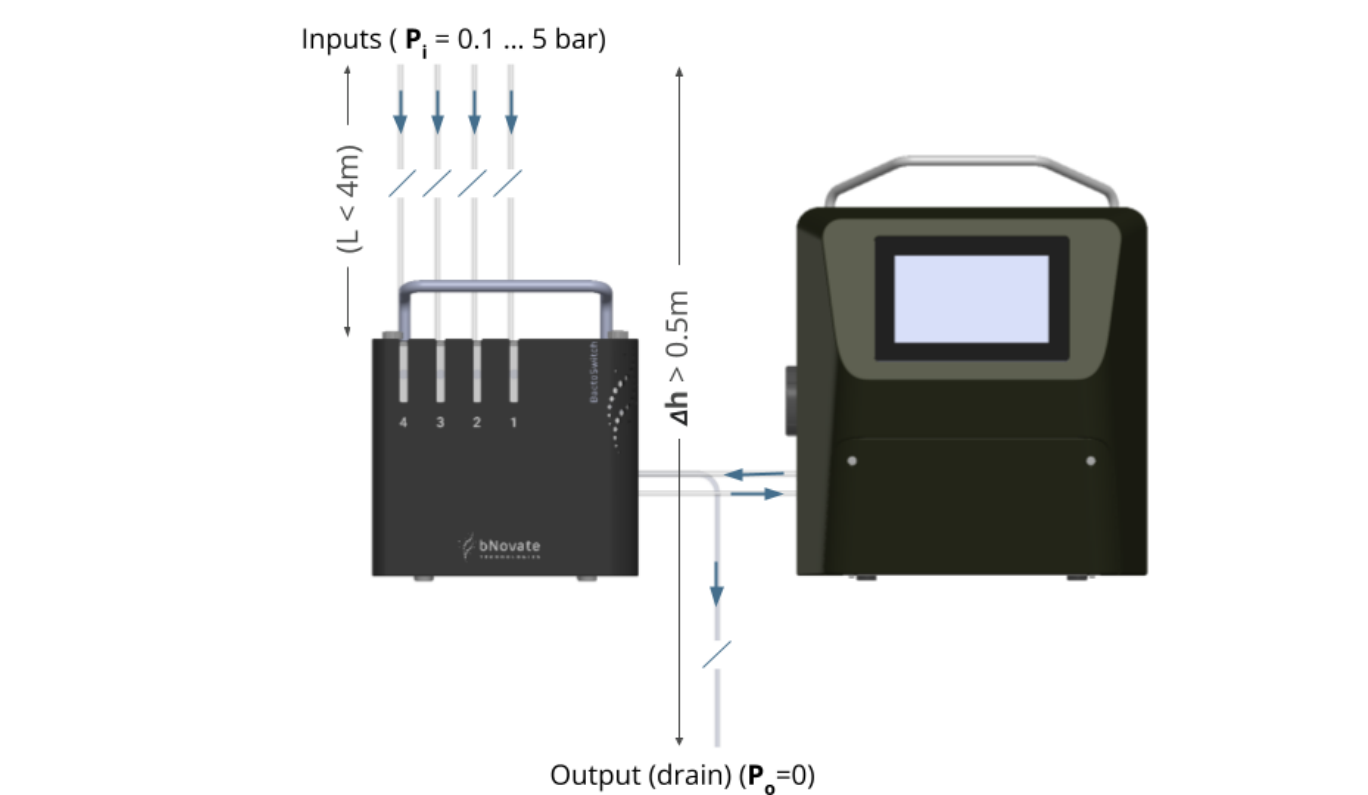
Figure 4-2 Overview of the fluidic lines installation
Please consider the following points:
- Tubings should be kept as short as possible. The maximum recommended length is 4 m (157.5″) for each tubing, but it depends on available pressure, bacterial load, etc.
- The input pressure range Pi of 0.1 … 5 bar assumes a minimum height difference Δh of 0.5 m between the inputs and the output. Every additional meter of height difference Δh reduces the needed input pressure Pi by approximately 0.1 bar.
- It is not necessary to have all 4 water inputs connected; the BactoSwitch can work with 2 or 3 inputs as well. However, the system needs to be configured appropriately. See Installation of the input lines.
Avoid contamination of the equipment. Wear nitrile gloves when handling tubings, the online sampling device, and any component which comes in contact with them.
Do not return drain to the water pipe system
Water diverted from the water system must not be returned to it after flowing through the BactoSwitch and BactoSense. Water from the output must go to a drain (used / waste water).
The BactoSwitch is equipped with check valves to prevent water from flowing from one line to another. However, a cross-contamination risk exists in case those valves fail. Customers should consider installing mitigation measures (e.g. double check valves) if that risk is not acceptable. Double check valves may require extra pressure.
Firmly attach tubings and sampling device
If the plumbing, tubings or sampling device are not tightly assembled or mounted, liquid can squirt and injure the user, or flood surrounding areas and cause material damage to nearby objects or infrastructure. All tube junctions must be carefully secured and tightened. The connections should be checked periodically after installation.
Inspect tubings following assembly
Pinched tubings can increase the flow resistance and reduce flow rates or prevent liquid from flowing at all. The tubings should be checked periodically for pinching after installation.
4.4.1 Installation of the output tubing (drain)
| WORK STEP | ADDITIONAL INFO / IMAGES | |
|---|---|---|
| 1. | Measure the tubing length needed from the BactoSwitch water output connector to the drain, considering that: • IMPORTANT: Water diverted from a drinking water pipe system must not be returned to the drinking water pipe system after flowing through the BactoSwitch; it must go to a drain (used water). | 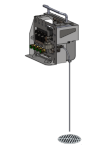 |
| 2. | Cut the tube to the desired length with the provided tube cutting tool, making sure that tubings are cut square to prevent leaks. Cut tubings square Make sure that tubings are cut square to prevent leaks or tubing detachment. |  |
| 3. | Insert the tube up to the fitting end-stop. Check the connection Pull back on the tubings to verify they are correctly connected. | 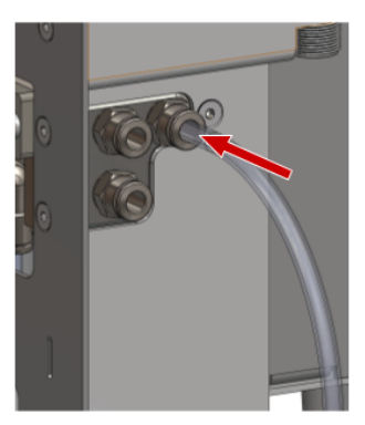 |
| 4. | Fix the other side of the tubing (output) in the drain. | The tubing output must not face any back pressure and the water must be free to flow out. |
4.4.2 Installation of the online sampling device
The BactoSwitch comes with a dedicated online sampling device with pre-cut (200 mm) and pre-installed tubings. This facilitates the installation, as the tubing length is adjusted to fit the installation hole pattern (Mounting the BactoSwitch with BactoSense on a wall or panel).
| WORK STEP | ADDITIONAL INFO / IMAGES | |
|---|---|---|
| 1. | Remove the manual sampling device from the BactoSense by: • unscrewing the knurled fixation ring and • pulling gently down. | 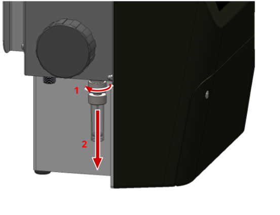 |
| 2. | • Use the sampling device with 200 mm pre-cut tubings supplied with the BactoSwitch. • Remove the protective cap from the online sampling device by loosening the knurled fixation ring (the protective cap cannot turn), and attach it to the manual sampling device of the BactoSense. | 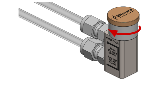 |
| 3. | Attach the BactoSwitch online sampling device to the BactoSense: • Insert the online sampling device in the sampling port of the BactoSense, carefully aligning the positioning pins of the online sampling device with the openings in the BactoSense sampling device port. • Tighten the knurled fixation ring until the sampling device is installed tightly. Finger-tight only Tighten by hand only. Do not use any tools. | 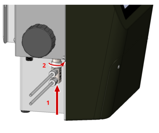 |
| 4. | • Insert both tubes up to the fitting end-stop. Check the connection Pull back on the tubings to verify they are correctly connected. | 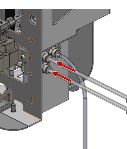 |
4.4.3 Installation of the input lines
Reduction fittings must be installed on the input (water pipe) side to accommodate the supplied PFA 6 mm OD tubing.
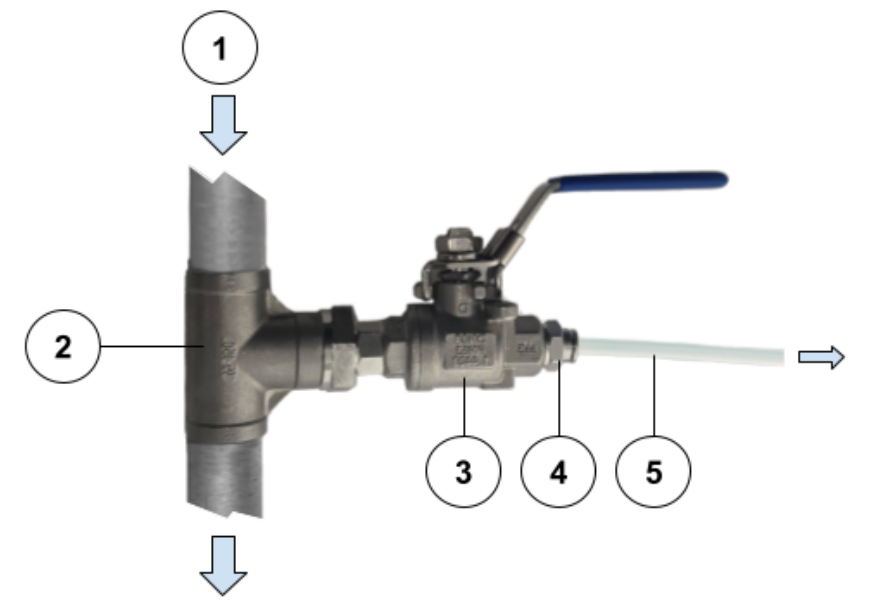
Figure 4-3 Typical input tubings installation, on source side
| # | DESCRIPTION |
|---|---|
| 1 | Existing line to monitor |
| 2 | T-junction |
| 3 | On/Off valve |
| 4 | Reduction fittings to ø6 mm tubing |
| 5 | PFA tubing to BactoSwitch ø6 mm x 1 mm |
| WORK STEP | ADDITIONAL INFO / IMAGES | |
|---|---|---|
| 1. | Define the tubing length needed from the BactoSwitch water input connectors to the water pipe reduction fittings. Consider the recommended maximum tubing length of 4 m when deciding where to place the instrument. | |
| 2. | Cut the tubes to the desired length with the provided tube cutting tool. Cut tubings square Make sure that tubings are cut square to prevent leaks or tubing detachment. | |
| 3. | Connect each tubing to the source side fittings (water pipes). | |
| 4. | On the BactoSwitch, insert each tubing up to the fitting end-stop. Check the connection Pull back on the tubings to verify they are correctly connected. | 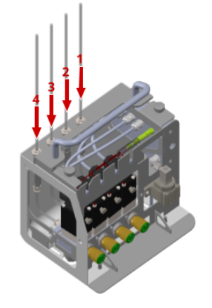 |
| 5. | Should any of the input lines be unused, the corresponding solenoid valve must be closed manually: • Press and hold the manual override. • Turn the manual override clockwise by 90° to switch the line off. The manual override is open when it is horizontal, closed when it is vertical. Note: Unused input lines must also be disabled in the BactoSense user interface, as explained in Line configuration. | 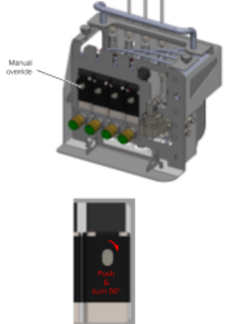 |
4.5 Electrical connections
Figure 4-4 provides a schematic illustration of the electrical connections. Detailed instructions for the connections are given below. Please refer to Connecting the BactoSense to power in the BactoSense user manual for more details.
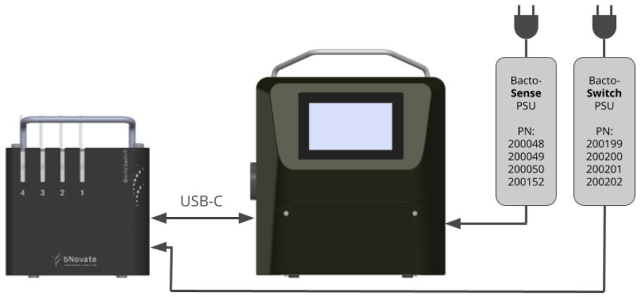
Figure 4-4 Schematic illustration of a BactoSwitch electrical installation
The BactoSwitch must be operated using the supplied original power supply unit (PSU) to ensure:
- Compliance with the applicable standards for safety, EMC, ingress protection and RoHS, as listed in Declaration of conformity, norms and classifications.
- Instrument performance according to bNovate instrument validation protocols.
- Warranty coverage.
Operation with alternative power supply units requires specific evaluation and permission by bNovate.
An uninterrupted and stable power supply as specified in Technical data must be guaranteed.
The BactoSwitch and the BactoSense each have their own power supply type, with different output voltages and different power connectors. They are not interchangeable!
Each power supply comes in an IP67 enclosure with a cable fitted with a type J, type E, type G or type B plug.
Table 4-2 Part numbers of BactoSwitch and BactoSense power supplies
| TYPE J (CH) | TYPE E (EU) | TYPE G (UK) | TYPE B (USA) | |
|---|---|---|---|---|
| BactoSwitch PSU | 200199 | 200200 | 200201 | 200202 |
| BactoSense PSU | 200048 | 200049 | 200050 | 200152 |
- The electrical plug or an additional circuit breaker should always be accessible to disconnect the main supply.
- The circuit breaker should respect the standards IEC60947-1 and IEC60947-3 and should protect a current of 10 A to 16 A.
- It is recommended that the transformer be connected to an electrical installation compliant with IEC 60364 and protected by a residual current device (RCD) with a rated residual operating current not exceeding 30 mA.
Note: The BactoSwitch does not have a power button; it is powered on as soon as its power supply unit is connected. It is detected by the BactoSense as soon as it is connected via the provided USB-C cable.
| WORK STEP | ADDITIONAL INFO / IMAGES | |
|---|---|---|
| 1. | Identify the power supplies of the BactoSwitch and the BactoSense, based on Table 4-2. | |
| 2. | Make sure both power supply units are dry and do not show any signs of damage. | |
| 3. | Plug the J, E, G or B-type plugs of the power supply units into a power source supplying the indicated voltage. | |
| 4. | Refer to Table 4-2 to identify the correct BactoSwitch power supply part number. Remove the cover of the BactoSwitch power connector, insert the power connector plug into the power connector socket, and fasten the locking ring. | 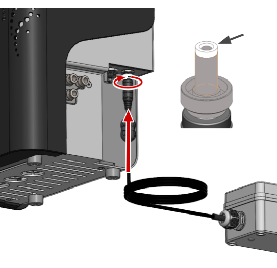 |
| 5. | Remove the cover of the BactoSwitch USB connector. Connect the supplied USB-C cable to the BactoSwitch and tighten the locking ring to secure it. | 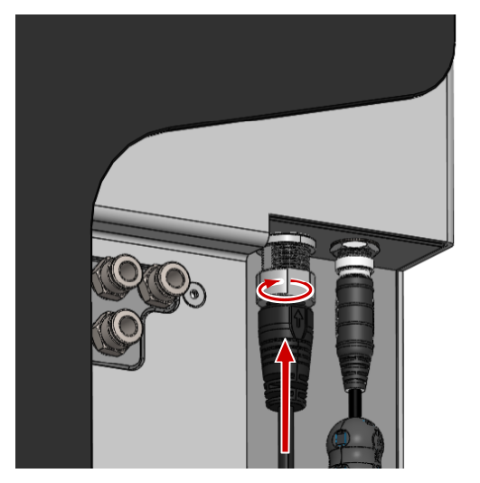 |
| 6. | Remove the cover of the USB-C connector on the left side of the BactoSense, insert the USB-C connector and tighten the locking ring to secure it. | 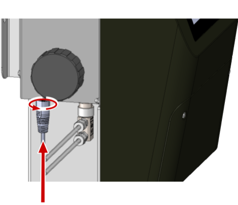 |
| 7. | Refer to Table 4-2 to identify the correct BactoSense power supply part number. Remove the cover of the power connector on the right side of the BactoSense, insert the power connector plug into the power connector socket, and fasten the locking ring. If the power connector is connected correctly and the instrument is powered, the instrument power button starts blinking. Please refer to the BactoSense user manual for more details. | 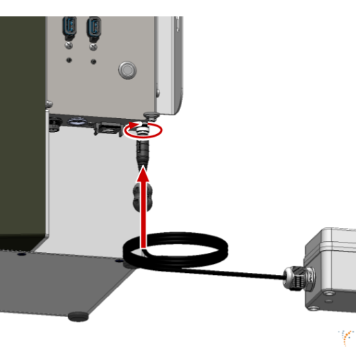 |
| 8. | To switch the BactoSense on, briefly press the power button. The BactoSense power button LED lights up constantly and after a few seconds, the welcome screen is displayed on the user interface. Please refer to the BactoSense user manual for more details. | 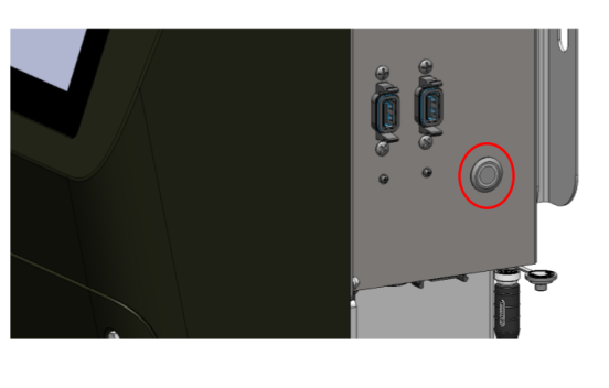 |
| 9. | If all connections are made correctly, the BactoSwitch status light turns green and the four line selection lights light up blue to indicate that the line valves are all open. | See Light indicators for more information on the status light operation. |
4.5.1 Modifying the standard power supply unit with a different connector
The following procedure only applies if the BactoSwitch shall be connected to a power source with a different plug than what has been delivered together with the standard power supply unit (J, E, G or B). In that case, the power supply unit is opened and the new connector installed manually.
- Only professional electricians are authorized to modify the power supply unit.
- It is forbidden to modify or repair the BactoSense instrument.
- Perform the work steps in the exact order instructed.
- Always use a plug with Protective Earth (PE).
- If the power supply cable is longer than 2 m, label it near the plug with the name of the device.
- If the power supply cable is longer than 20 m, the impedance of PE needs to be smaller than 0.2 Ω.
| WORK STEP | ADDITIONAL INFO / IMAGES | |
|---|---|---|
| 1. | Disconnect the power supply Ensure that the power supply is not connected to power. | 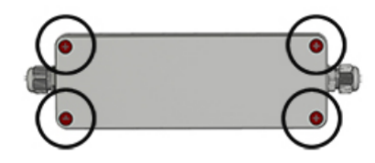 |
| 2. | Remove the C13 connector (A) and unscrew it to open.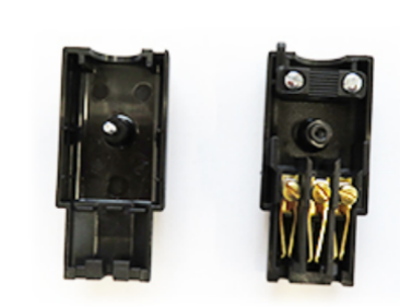 | 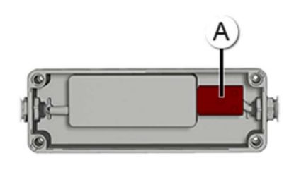 |
| 3. | Open the cable connector (Y) and insert the new cable. Cable lengths and wire cross sections: • 0 – 9 m (0 – 30 ft), 1 mm2 • 9 – 21 m (30 – 69 ft), 1.5 mm2 (maximal) The cable connector is dimensioned for a cable diameter of 3 – 10 mm (0.12″ – 0.39″). | 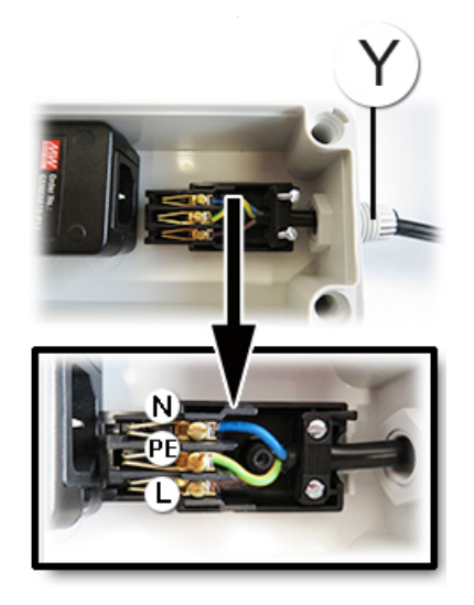 |
| 4. | Connect protective earth Tighten the 3 wires (N, PE, L) in the electrical terminal and secure the cable insulation. | See the inset in the image above. |
| 5. | Close the C13 connector (A) using the screw and plug it into the power supply. Tighten the cable connector. Try to pull the cable to assess whether the cable connector is tight enough. | 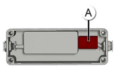 |
| 6. | Optional: the power supply can be mounted on a wall. M4 screws should be used with a minimum length of 20 mm. With the cover still removed, place the 4 screws and fix the enclosure to the wall. | 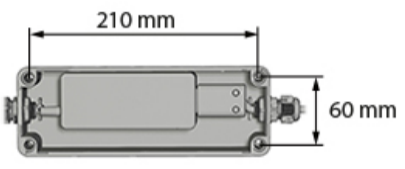 |
| 7. | Put the cover of the enclosure back and tighten the four screws to seal it. | |
| 8. | Connect the power supply unit to power and the instrument as described in Electrical connections. |
4.6 Line configuration
The following sections show examples of the BactoSense user interface. They assume that you are familiar with the BactoSense and only focus on BactoSwitch operation. Please refer to the BactoSense user manual for more information.
Log in to the BactoSense in Admin mode. In Settings, select Online mode settings.
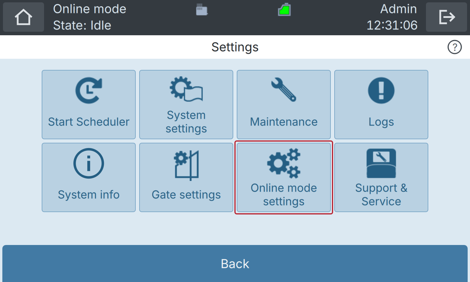
Next, select BactoSwitch sample lines:
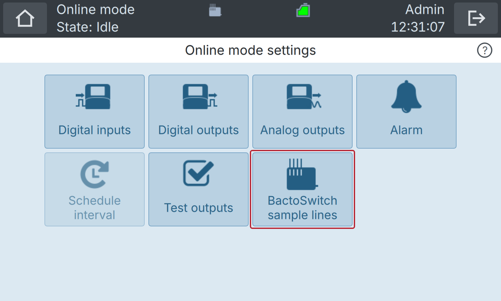
The BactoSense detects the BactoSwitch automatically as soon as it is connected and powered (see Electrical connections); the BactoSwitch icon then appears in the top toolbar.
On the BactoSwitch sample lines page you can:
- Enable or disable a line. Lines that are not physically connected must be closed with the manual override (as explained in Installation of the input lines) and must be unchecked here.
- Rename the lines.
- Change the color that is used to plot the lines in the graphs.
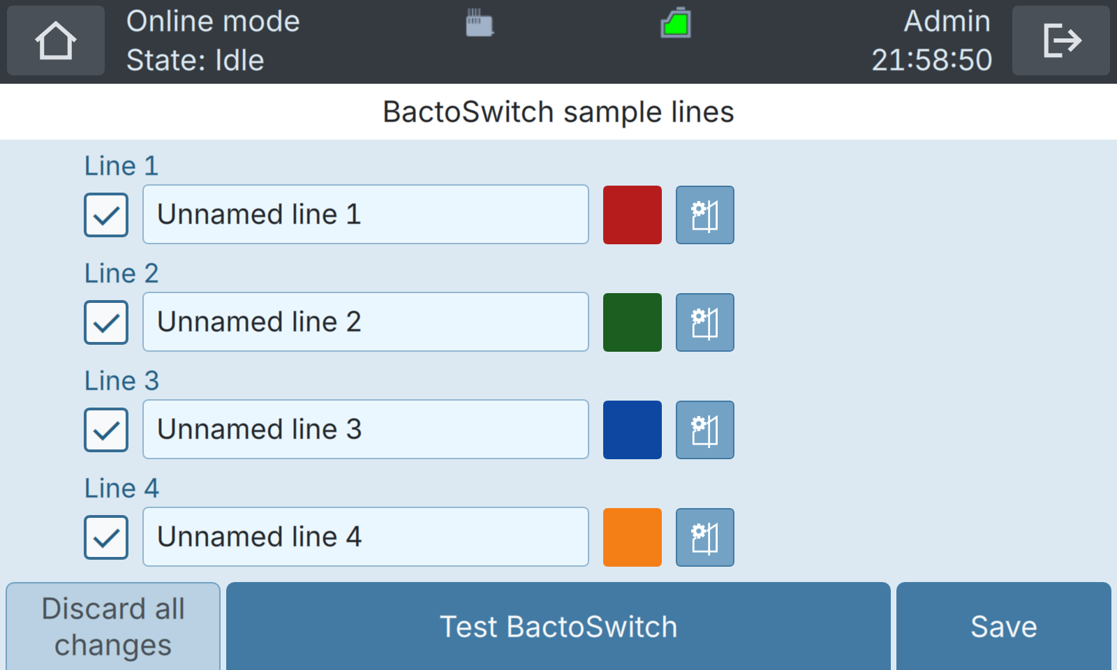
Press Save to store the changes. While the advanced scheduler is enabled, the lines cannot be edited on this page.
4.7 Priming water in the system
Carefully open the On/Off valves at your sampling points to let water flow through the system, and carefully check the appliance for leaks at the:
- Input lines connectors (#2 in Figure 2-1)
- Tubings between the BactoSwitch and the BactoSense (#8 and #9 in Figure 2-1)
- Output to drain tubing connector (#10 in Figure 2-1)
- Online sampling device connection to the BactoSense (see work step 3 in Installation of the online sampling device)
Also, watch for any water puddle forming below the BactoSwitch and the connection to the BactoSense.
If any leak appears, close the On/Off valves at your sampling points before troubleshooting.
Note that the solenoid valves inside the BactoSwitch are all open by default (NO = “Normally Open”), so water should flow freely from the inputs to the drain.
4.8 Line testing and flow setting
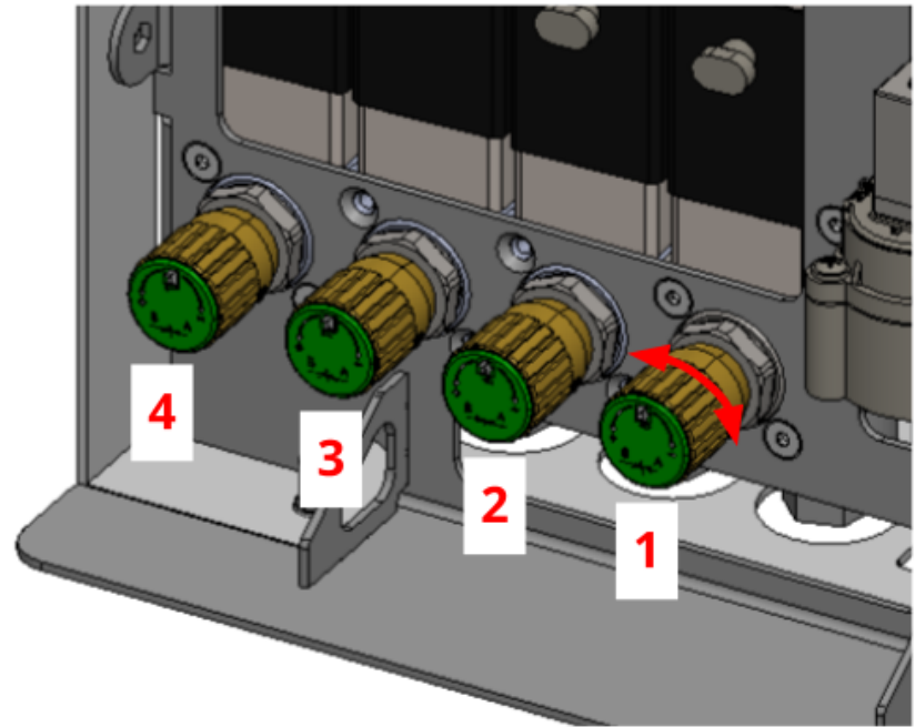
To test or set the flow rate using the built-in needle valves of the BactoSwitch, remove the front cover (if not already removed).
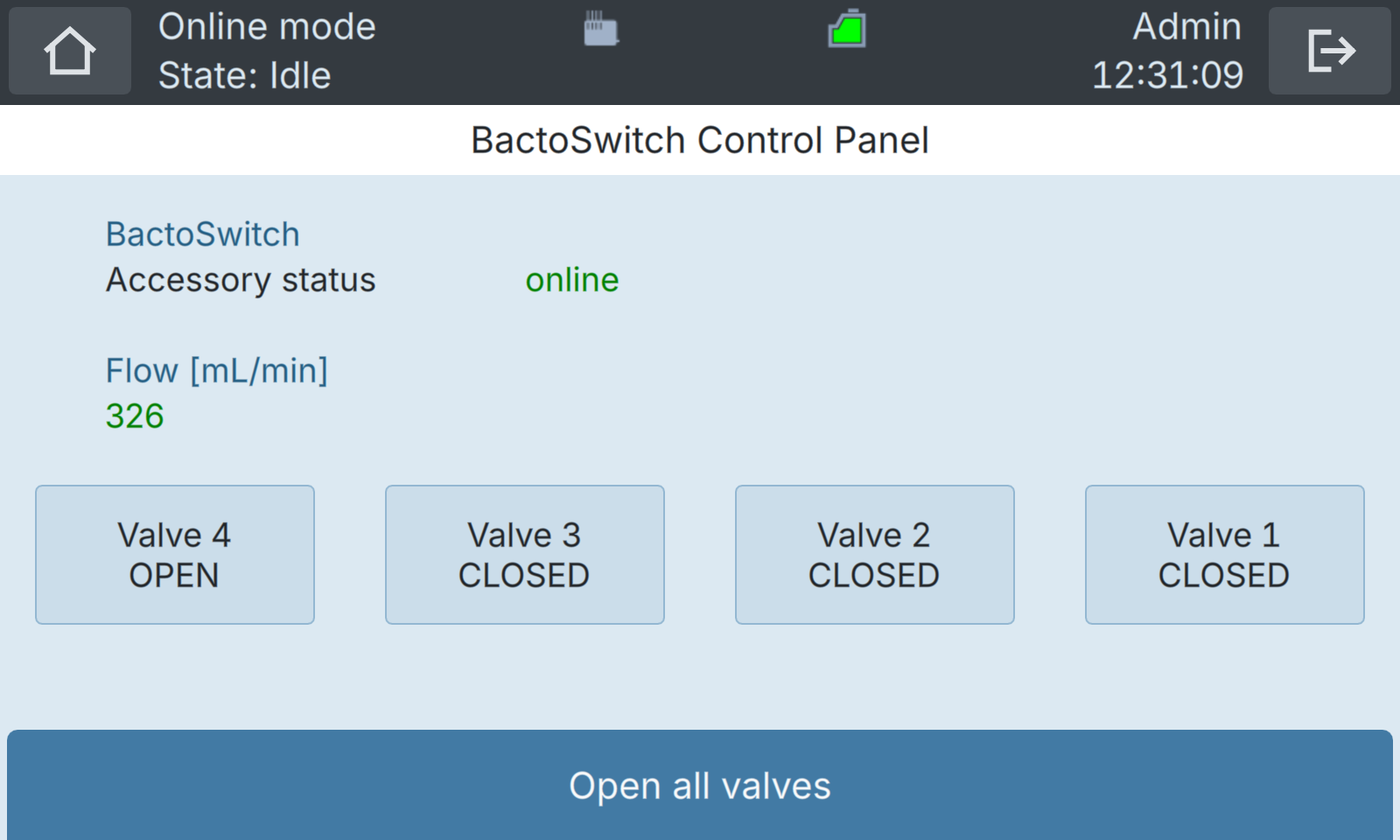
Then, on the BactoSense user interface, enter the BactoSwitch sample lines menu (see Line configuration), and press the Test BactoSwitch button. This opens the BactoSwitch Control Panel. The four valve buttons allow you to open only the selected valve, while the others are closed automatically. To re-open all valves, press the Open all valves button at the bottom of the screen.
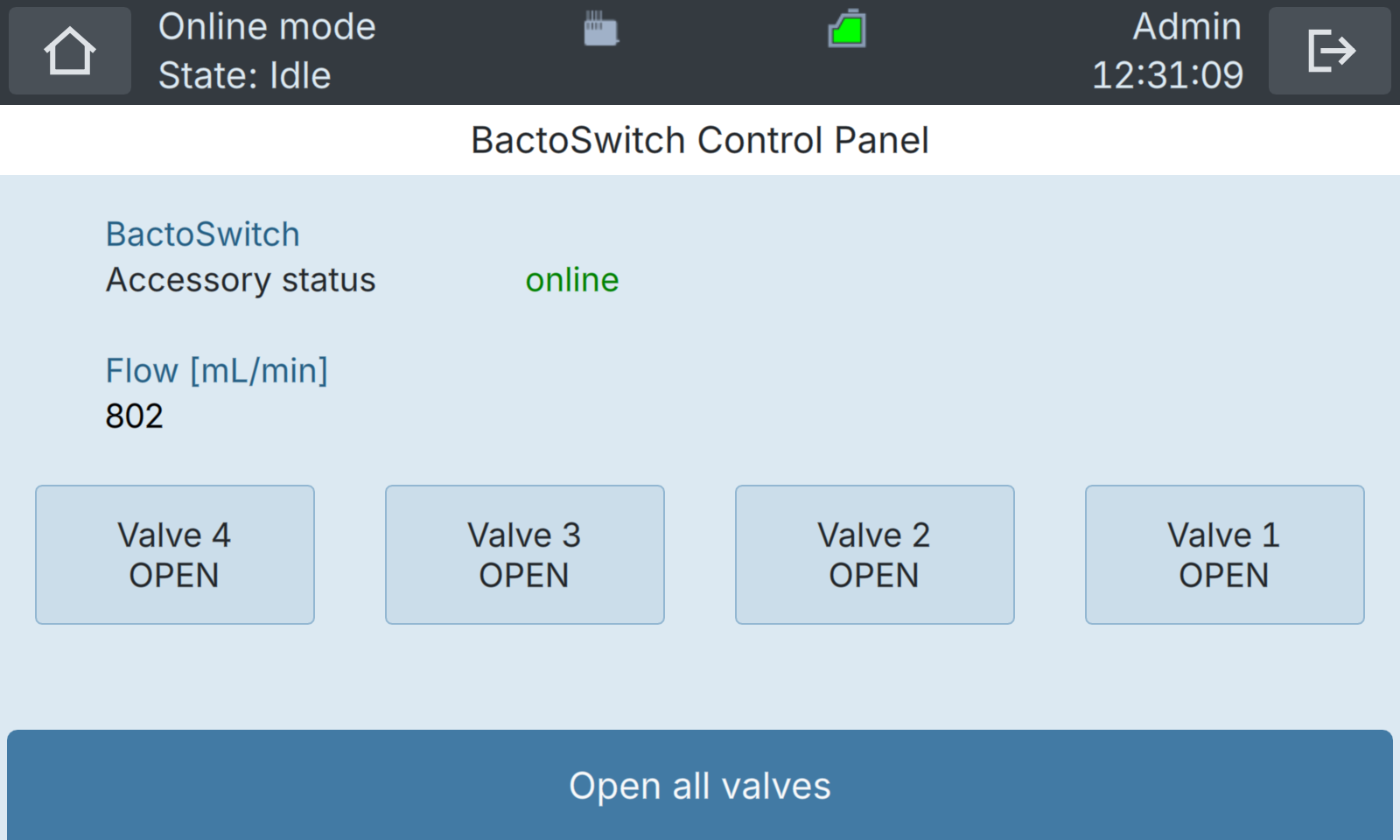
When only one of the valves is open, the indicated flow rate value turns green or red, depending on whether the flow rate is within the specified values of 150 – 400 mL/min or not:
To adjust the flow rate of each input line, use the adjustment knobs of the BactoSwitch (see figure below) until the flow rates are within the 150 – 400 mL/min range, ideally about 300 mL/min.
Notes:
- If the pressure drop is above 0.3 bar, the flow rate should adjust automatically within the limits after factory calibration.
- If you cannot reach 150 mL/min, this is likely because the pressure drop across the device is too low. Increase the input pressure or Δh (see Figure 4-2).
Finally, place the front cover back and secure it with the two knob screws: